
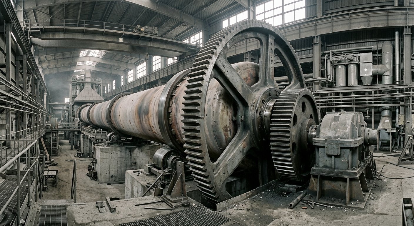
Der Ofenlaufkranz: Grundlagen des Antriebssystems
Antriebssystem für Drehrohrofen-Zahnkranz und Ritzel: Einzel- vs. Doppelantrieb, Ausrichtung, Zahnflankenspiel und Schmierung für Zementdrehrohröfen.
Der Ofenlaufkranz ist ein großes, offenes Zahnrad, das auf den Ofenmantel aufgeschraubt ist und mit einem Antriebsritzel kämmt. Er überträgt das Motordrehmoment, um den Ofenmantel unter Volllast mit 1–4 U/min zu drehen. Er ist eine der kapitalintensivsten Komponenten des Ofens mit der längsten Lieferzeit: Der Austausch eines Laufkranzes erfordert 12–18 Monate von der Bestellung bis zur Lieferung [1]. Dieser Artikel behandelt die Funktion des Laufkranzes, Einzel- vs. Doppelantriebskonfigurationen, Ausrichtungsprinzipien einschließlich Kopfspiel, Schmierung und Verschleißüberwachung.
Funktion des Laufkranzes
Der Laufkranz ist ein geteiltes Zahnrad (hergestellt in zwei Hälften für die Montage vor Ort und den späteren Ausbau), das konzentrisch auf dem Ofenmantel zwischen zwei Laufstationen montiert ist. Das Ritzel, das von einem Getriebe und einem Motor angetrieben wird, kämmt mit dem Laufkranz und dreht den Ofen.
Ofenlaufkranz: ein großes, offenes Zahnrad, typischerweise mit einem Teilkreisdurchmesser von 3–5 m, das auf dem Drehrohrofenmantel montiert ist und von einem Ritzel angetrieben wird, um den Ofen mit 1–4 U/min zu drehen. Zur Montage vor Ort in zwei Hälften gefertigt.
Typische Parameter für Laufkränze großer Zementöfen:
- Teilkreisdurchmesser: 3–5 m [2]
- Modul: 20–50 (großer Modul für hohe Drehmomentkapazität)
- Zähnezahl: 120–200+ (hohe Zähnezahl für ruhigen Zahneingriff)
- Material: gegossener oder geschmiedeter Mn-Cr- oder Mn-Ni-Cr-legierter Stahl, oberflächengehärtet
Das Zahnrad wird mittels tangentialer Federbleche oder durch direkte Verschraubung am Mantel befestigt, was eine geringfügige differenzielle Ausdehnung zwischen Zahnrad und Mantel während der Heiz- und Kühlzyklen ermöglicht.
Der Zementherstellungsprozess erfordert eine kontinuierliche, zuverlässige Ofendrehung. Ein Ausfall des Laufkranzes stoppt die Produktion sofort; ein ungeplanter Stillstand bei einem 5.000-t/Tag-Ofen hat direkte Auswirkungen auf den spezifischen Brennstoffverbrauch (der Ofen muss neu angefeuert und wieder auf Temperatur gebracht werden, was zusätzlichen Brennstoff verbraucht) und kostet pro Tag mehr an entgangenem Ertrag als das Zahnrad selbst.
Einzel- vs. Doppelantriebskonfigurationen
Eine Einzelantriebskonfiguration verwendet eine Motor-Getriebe-Ritzel-Einheit, die mit dem Laufkranz kämmt. Eine Doppelantriebskonfiguration verwendet zwei Ritzelbaugruppen im 180°-Winkel, wodurch die Last pro Zahnkontakt halbiert und das Biegemoment des Mantels unter Drehmoment reduziert wird.
Antriebsstrangsequenz (beide Konfigurationen):
Motor → Fluidkupplung (oder Frequenzumrichter) → Hauptgetriebe → Ritzel → Laufkranz → Ofenmantel
Der Einzelantrieb ist bei Öfen bis ca. 5.000 t/Tag Standard [3]. Das gesamte Motordrehmoment wird über einen Zahneingriff übertragen. Dies konzentriert die Zahnlast und die Mantelverformungskraft an einer Umfangsposition.
Der Doppelantrieb verteilt die tangentiale Zahnlast auf zwei Ritzel im 180°-Winkel, wodurch das Netto-Biegemoment auf den Mantelquerschnitt um ca. 50 % reduziert wird [3]. Dies ist die bevorzugte Konfiguration für große Öfen (5.000+ t/Tag) und für Öfen mit hoher Drehmomentvariabilität durch die Befeuerung mit alternativen Brennstoffen, bei denen Lastspitzen erheblich sein können.
Jeder Ofen verfügt zudem über einen Hilfsantrieb (Drehwerk): einen Motor mit niedriger Drehzahl und niedrigem Drehmoment für die langsame Drehung während Stillständen, Wartungsarbeiten und zum Temperaturausgleich. Das Drehwerk schützt den Mantel und die Ausmauerung vor thermischer Verformung während Stopps und Wiederanfahrvorgängen.
| Parameter | Einzelantrieb | Doppelantrieb |
|---|---|---|
| Zahnlast pro Eingriff | Volle Tangentialkraft | ~50 % der Tangentialkraft je |
| Mantelbiegemoment | Höher an der Zahnradstation | Um ~50 % reduziert |
| Ausrichtungskomplexität | Einfacher (ein Ritzel) | Höher (zwei Ritzel müssen synchronisiert werden) |
| Typische Anwendung | Öfen bis ca. 5.000 t/Tag | Große Öfen, hohe Drehmomentvariabilität |
| Kapitalkosten | Niedriger | Höher |
Quelle: cementl.com Drehrohrofen-Antriebstypen [3]; Industriepraxis.
Ausrichtungsprinzipien
Eine korrekte Ausrichtung des Laufkranzes erfordert, dass die Achsen von Zahnrad und Ritzel innerhalb der OEM-Toleranzen parallel verlaufen und das Kopfspiel über den gesamten Umfang des Zahnrads gleichmäßig ist.
Das Kopfspiel ist der radiale Abstand zwischen der Spitze eines Zahnradzahns und dem Grund des kämmenden Zahnrads. Die Berechnungsformel:
c = 0,25 × m + (2 bis 3 mm)
Wobei:
c= Kopfspiel [mm]m= Zahnradmodul [mm/Zahn]
Für ein Zahnrad mit Modul 30: c = 0,25 × 30 + 2 = 9,5 mm (Minimum). Typischer Bereich für große Zementofen-Zahnräder: 5–15 mm [4][5].
Das Flankenspiel (Zahnseitenspiel) für die Erstmontage: 0,2–0,5 mm [4][5]. Das Flankenspiel nimmt mit dem Verschleiß zu; sobald das Zahnrad eingelaufen ist, wird die Ausrichtung eher durch Überwachung des Kopfspiels als des Flankenspiels beibehalten.
Das Tragbild wird mit Tuschierpaste (Preußischblau auf die Ritzelzähne aufgetragen; der Abdruck auf dem Zahnrad zeigt die Kontaktzone) geprüft:
- Mindestens 60 % Kontakt entlang der Zahnlänge [4]
- Mindestens 40 % Kontakt entlang der Zahnhöhe [4]
Ein ungleichmäßiges Kopfspiel über den Umfang deutet auf Exzentrizität des Zahnrads, Unrundheit des Mantels oder eine fehlerhafte Montage hin. Dies muss vor der Inbetriebnahme korrigiert werden; der Betrieb eines falsch ausgerichteten Zahnrads beschleunigt Kantenverschleiß und Zahnermüdung.
Thermische Ausdehnung verändert den Ausrichtungszustand zwischen Kalt- und Heißbetrieb. Die anfängliche Ausrichtung erfolgt im kalten Zustand mit einer vom OEM berechneten Kompensation für den Unterschied in der thermischen Ausdehnung zwischen der Zahnradmontage auf dem heißen Mantel und dem Ritzel auf seiner kühleren Welle. Eine Nachprüfung bei Betriebstemperatur ist Standardpraxis.
Die Ausrichtung der Laufringe beeinflusst direkt die Ausrichtung des Laufkranzes, da sowohl die Laufringe als auch das Zahnrad auf demselben Mantel montiert sind. Siehe Funktion und Verschleiß von Ofenlaufringen für Informationen darüber, wie sich Einstellungen an den Laufstationen auf die Mantelachse auswirken.
Schmierung
Der Laufkranz ist ein offenes Zahnrad: Er ist der Prozessumgebung ausgesetzt und erfordert ein intermittierendes Sprühschmiersystem.
Schmierstofftyp: hochviskoser Schmierstoff für offene Getriebe, typischerweise ISO VG 1500-3200 oder höher, bituminöse oder synthetische Formulierung [6][7]. Der Schmierstoff muss trotz Schwerkraft, Zentrifugalkraft und Staubbelastung während des Eingriffs an den Zahnflanken haften.
Auftragssystem: automatische Sprühdüsen, die in zeitlichen Abständen ausgelöst werden. Die Sprühtaktung zielt auf ein oder zwei vollständige Ofenumdrehungen pro Sprühzyklus ab, um alle Zähne zu benetzen [7]. Die AGMA-Norm 9005-D94 spezifiziert ein maximales Intervall von zwei Stunden zwischen den Sprühanwendungen [6].
Staub, Zement und thermische Wechselbelastung sind die Hauptfaktoren für Schmierstoffkontamination und -abbau. Die Verstopfung der Sprühdüsen durch Zementablagerungen ist die häufigste Wartungsstörung am Schmiersystem; die Düsen sollten bei jeder Ofeninspektionsrunde überprüft werden.
Die Schmierstoffmenge wird gemäß AGMA 9005-Tabellen basierend auf der Teilkreisgeschwindigkeit, dem Zahnraddurchmesser und der Nennmotorleistung bemessen [6]. Mangelschmierung ist die Hauptursache für Verschleiß an Laufkranz und Ritzel; Überschmierung verschwendet Schmierstoff und begünstigt Staubablagerungen.
Oswals Wartungs- und Inspektionsservice umfasst Schmiersystemprüfungen als Teil der mechanischen Ofenaudits für Zementwerke und andere Betreiber von Drehrohröfen.
Verschleißüberwachung und Fehlerarten
Die drei primären Fehlerarten des Laufkranzes sind: Grübchenbildung (Pitting, Oberflächenermüdung), Zahnverschleiß (abrasiv) und Rissbildung (Stoßbelastung oder Fehlausrichtung).
Grübchenbildung (Pitting): Oberflächenermüdung durch Überlastung (Fehlausrichtung konzentriert die Last auf eine Zahnflanke) oder Zusammenbruch des Schmierfilms. Pitting im Frühstadium ist durch die Tragbildprüfung erkennbar. Wenn es nicht korrigiert wird, schreitet Pitting zu Ausbrüchen (Spalling) fort.
Zahnverschleiß (abrasiv): Zementstaub, der in den Eingriff gelangt, wirkt abrasiv und verschleißt das Zahnprofil. Das Kopfspiel nimmt ab, während die Zahnspitze verschleißt. Die Trendanalyse des Kopfspiels ist das primäre Maß für den Verschleiß.
Rissbildung: verursacht durch Stoßbelastungen (hartes Fremdmaterial im Eingriff) oder durch Fehlausrichtung induzierte Biegeermüdung. Oberflächenrisse erfordern eine sofortige UT- oder MT-Prüfung, um die Ausbreitungstiefe zu beurteilen.
Überwachungsparameter:
| Parameter | Messmethode | Korrekturschwelle |
|---|---|---|
| Kopfspiel | Fühlerlehre oder Lasermessung | >150 % der OEM-Spezifikation |
| Tragbild | Tuschierabdruck | Kontakt <50 % Zahnlänge oder <35 % Höhe |
| Schwingung (Zahneingriffsfrequenz) | Beschleunigungsaufnehmer am Getriebelager | Amplitudentrend steigend >25 % |
| Schmierstoffverbrauch | Durchflussmesser oder Tankfüllstand | Unter der minimalen AGMA-Menge |
Wenden des Zahnrads: Der Laufkranz kann um 180° gewendet werden, wenn eine Zahnflanke verschlissen ist, was die Lebensdauer verdoppelt. Dies wird im langfristigen Wartungsplan berücksichtigt.
Ritzel-Austauschintervall: Ritzel werden häufiger ausgetauscht als der Laufkranz (kleiner, kostengünstiger, besser zugänglich). Ein Ersatzritzel vor Ort vorzuhalten ist Standardpraxis und verhindert lange ungeplante Stillstände.
Austauschplanung: Ein neuer Laufkranz erfordert 12–18 Monate von der Bestellung bis zur Lieferung [1]. Die Budgetplanung sollte beginnen, wenn das Kopfspiel oder Pitting anzeigt, dass das Zahnrad etwa 70 % seiner geschätzten Lebensdauer erreicht hat.
Common questions about this topic
Das Kopfspiel ist der radiale Abstand zwischen dem Zahnkopf eines Zahnrads und dem Zahnfuß (Fußkreis) des im Eingriff stehenden Gegenrads. Bei Ofengroßrädern beträgt der Konstruktionswert etwa das 0,25-fache des Moduls zuzüglich 2–3 mm [4][5]. Für ein Zahnrad mit Modul 30 ergibt dies etwa 9,5–10,5 mm. Das Kopfspiel wird regelmäßig mit einer Fühlerlehre gemessen; ein zunehmender Trend deutet auf Zahnkopfverschleiß hin. Wenn das Kopfspiel 150 % des vom Erstausrüster (OEM) vorgegebenen Konstruktionswerts überschreitet, sollte die Position des Ritzels angepasst (durch Unterlegen von Passscheiben nach innen verlagert) oder ein Austausch eingeplant werden.
Ein Einzelantrieb verwendet eine Motor-Getriebe-Ritzel-Einheit, die in den Zahnkranz eingreift und die gesamte Umfangszahnkraft an einer Position konzentriert [3]. Ein Doppelantrieb nutzt zwei Ritzelbaugruppen im 180°-Versatz, wodurch die Zahnkraft pro Eingriffspunkt annähernd halbiert und das Biegemoment auf den Ofenrohrquerschnitt reduziert wird. Doppelantriebe sind bei großen Drehrohröfen ab einer Kapazität von etwa 5.000 t/Tag sowie bei Öfen, bei denen eine hohe Drehmomentvariabilität durch den Einsatz von Ersatzbrennstoffen eine Spitzenlastregelung erforderlich macht, Standard.
Die AGMA-Norm 9005-D94 schreibt für offene Getriebe ein maximales Intervall von zwei Stunden zwischen den Sprühschmierungen vor [6]. Die Funktion der Sprühdüsen sowie der Schmierstoffstand sollten bei jedem Inspektionsrundgang des Ofens, üblicherweise alle 4–8 Stunden im Dauerbetrieb, überprüft werden. Vollständige Überprüfungen des Schmiersystems, einschließlich des Düsenzustands, der Schmierstoffverbrauchsrate und des Sprühbildes auf der Zahnflanke, sind Bestandteil geplanter Wartungsstillstände. Eine unzureichende Schmierfrequenz ist die Hauptursache für beschleunigten Zahnverschleiß.
Sources
- Philadelphia Gear, "Replacing a Kiln's Massive Gear Drive," case study. Lead time and replacement planning references
- Hofmann Engineering, "Mill & Kiln Girth Gears to 15m (50ft)." Manufacturer technical brochure: girth gear sizing range, materials (forged fabricated steel, SGI, cast steel), and finish machining for cement kilns and mills.
- CEMENTL, "Rotary Kiln Drive Type: Girth Gear Pinion, Friction, Hydraulic, Chain Sprocket." Single vs dual drive configurations and typical applications
- AGICO / cementequipments.com, "How to Adjust the Meshing of the Kiln Girth Gear?" Root clearance formula, backlash, and contact pattern criteria
- CEMENTL, "Ball Mill Girth Gear, Crown Gear, Pinion, and Ring Gear for Rotary Kiln." Tooth side clearance and contact pattern specifications
- Machinery Lubrication / AGMA 9005-D94, "Applying Open Gear Lubricants." Maximum spray interval, lubricant quantity sizing
- INFINITY for Cement Equipment / The Cement Institute, "Applying Open Gear Lubricants." Spray cycle guidance and lubricant types
Verwandte Artikel
Discuss Your Sealing Requirements
Our engineering team can help identify the right sealing solution for your application.
Contact Engineering Team“Überall dort, wo Hochtemperatur-Drehrohröfen unter kontrollierter Atmosphäre betrieben werden, sorgen Oswal-Dichtungssysteme für Energieeffizienz und Prozessstabilität.”