
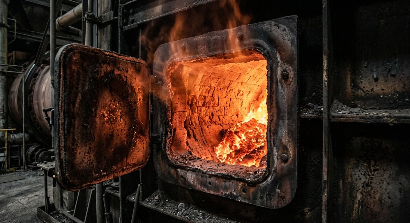
Identifizierung von Ringbildungen in Zementdrehrohröfen
Ofenringe reduzieren den Durchsatz und erzwingen Stillstände. Identifizierung von Ansatzringen in der Beschickungs-, Klinker-, Asche- und Kühlzone im laufenden Betrieb sowie deren Ursachenanalyse.
Ein Drehrohrofenring ist eine ringförmige Ablagerung aus anhaftendem Klinker, Rohmehl oder Flugasche, die sich auf der Ofenausmauerung aufbaut und den Gasströmungsquerschnitt verengt. Starke Ringbildungen reduzieren den Durchsatz, erhöhen den Gegendruck am Saugzuggebläse, beschädigen beim Ablösen die Ausmauerung und führen im schlimmsten Fall zu ungeplanten Stillständen.
Dieser Leitfaden dient der Identifizierung von Ringbildungen während des laufenden Zementherstellungsprozesses: Er erläutert die vier Ringtypen, die für den Anlagenfahrer beobachtbaren Signale, die auf einen Ring hindeuten, bevor dieser entfernt werden muss, sowie die chemischen Prozesse, die das Wachstum begünstigen.
Was ein Ofenring ist und warum er von Bedeutung ist
Ein Ofenring ist eine verhärtete, ringförmige Anbackung, die den Gasströmungsquerschnitt verengt. Ein dünner Belag aus erstarrter Klinkerschmelze in der Sinterzone ist erwünscht, da er die Ausmauerung schützt; ein Ring entsteht, wenn dieser Belag so stark anwächst, dass er in den freien Ofenquerschnitt hineinragt.
Ofenring: Eine anhaftende Ablagerung aus Klinker, Rohmehl oder Asche auf der inneren Ausmauerung eines Drehrohrofens, die den Ofenquerschnitt verengt. Dies ist abzugrenzen von einem gesunden Sinterzonenbelag, der dünn und schützend ist.
Ein 0,5 m dicker Ring in einem Ofen mit 4,5 m Innendurchmesser entspricht einer Reduzierung der freien Querschnittsfläche um etwa 40 % an dieser Stelle. Deshalb ist ein schleichender Anstieg des Gegendrucks am Saugzuggebläse eines der frühesten Warnsignale.
Die vier Ringtypen und ihre Entstehungsorte
Zementofenringe werden nach ihrer Position entlang der Ofenachse und dem dominierenden Bindemechanismus klassifiziert. Vier Typen decken fast alle Beobachtungen in der Praxis ab: Materialringe (Mehlringe) nahe dem Einlauf, Ascheringe in der Sinterzone, Klinkerringe (Sinterringe) in der oberen Übergangszone und Kühlzonenringe nahe dem Ofenauslauf. (Cementequipment.org, Coating and Ring Formations in a Rotary Kiln, basierend auf Holderbank-Schulungsunterlagen.)
| Ringtyp | Position entlang der Ofenachse | Typische Ursache | Diagnosesignal |
|---|---|---|---|
| Materialring (Mehlring) | Ofeneinlauf / Kalzinierzone | Klebriges Rohmehl bei intermediärer Kalzinierung; hoher Kalkstandard (LSF) oder Silikatmodul (SR); Kreislauf flüchtiger Bestandteile | Drift der Ofeneinlasstemperatur; Gasströmungsbehinderung am Einlauf |
| Aschering | Sinterzone | Brennstoffaschechemie inkompatibel mit Klinker (aschekohlenreich, Vanadium-Petkoks) | Belagsverfärbung am Ofenmantelscanner; Ascheanalyse bei Ofenstillständen |
| Klinkerring (Sinterring) | Obere Übergangszone, ca. 7-11 Ofendurchmesser vom Auslauf entfernt | Übermäßige Erstarrung der Flüssigphase; S/A-Molverhältnis außerhalb des Sollbereichs | Anstieg der Ofenstromaufnahme; Anstieg des Gegendrucks am Saugzuggebläse; Kaltstelle am Ofenmantelscanner |
| Kühlzonenring (Nasenring) | Nahe Auslauf / Ofenkopf | Klinker unzureichend gekühlt vor Erreichen des Ofenkopfes; S/A-Ungleichgewicht | Abfall der Sekundärlufttemperatur; Abfall der Klinkertemperatur am Kühleinlauf |
Der Klinkerring ist der häufigste und schädlichste Typ. Er befindet sich in der oberen Übergangszone, etwa 7-11 Ofendurchmesser vom Auslauf entfernt (bei einem 5-m-Ofen etwa 35-55 m), und die Ablagerung selbst ist typischerweise 15-20 m lang. Das Bindemittel ist die flüssige Klinkerphase, die bei Temperaturen unter ca. 1250 °C auf der Ausmauerung erstarrt, während feiner Klinkerstaub aus der Sinterzone zurückgetragen wird (Cementequipment.org, Rings, Balls and Build-Ups). Ein verwandter Subtyp, der Sinterring, bildet sich weiter vorne (4-5 Ofendurchmesser vom Auslauf, wo die Flüssigphase bei ca. 1280 °C erstmals auftritt). Sulfat- und alkalibedingte Untervarianten des Klinkerrings werden durch das molare Schwefel-Alkali-Verhältnis (S/A) im Ofengas unterschieden: Alkaliringe dominieren bei einem S/A-Verhältnis unter ca. 0,83, Sulfatringe bei einem S/A-Verhältnis über ca. 1,2 (Larsson, Counteracting Ring Formation in Rotary Kilns).
Identifizierung eines Rings im laufenden Betrieb ohne Stillstand
Anlagenfahrer identifizieren eine Ringbildung in einem laufenden Ofen anhand von vier Routineindikatoren: steigende Stromaufnahme des Ofenantriebs, erhöhter Gegendruck am Saugzuggebläse, Muster von Heiß- oder Kaltstellen auf dem Ofenmantelscanner sowie Abweichungen bei der Sekundärlufttemperatur und der Ofeneinlasstemperatur.
- Stromaufnahme des Ofenantriebs. Der einfachste Indikator und erfahrungsgemäß das zuverlässigste Einzelsignal in der Praxis: Die zusätzliche Masse und die veränderte Gewichtsverteilung durch den Ring erhöhen das Drehmoment, das zum Drehen des Ofens erforderlich ist. Das Signal ist jedoch nicht spezifisch. Die Stromaufnahme driftet auch bei allgemeinem Belagswachstum, Ausmauerungsverschleiß und Änderungen der Klinkergröße, daher muss sie zusammen mit den anderen Indikatoren bewertet werden (Cement Plant Operation Handbook, cementkilns.co.uk; Cementequipment.org, Kiln Control and Operation).
- Anstieg des Gegendrucks am Saugzuggebläse. Ein schleichender Anstieg der Leistungsaufnahme des Saugzuggebläses bei konstantem Durchsatz und unverändertem Falschluftstatus deutet auf eine Strömungsbehinderung im Ofen hin. Zuerst sollte eine Änderung der Falschluft ausgeschlossen werden; ist das O₂-Profil stabil und der Gegendruck steigt dennoch, ist ein Ring die wahrscheinlichste Ursache.
- Ofenmantelscanner. Infrarot-Mantelscans zeigen einen Ring als Kaltstelle (die Ablagerung isoliert den Stahlmantel gegen die Strahlung der Sinterzone) oder als scharfen axialen Temperaturgradienten. Mantelüberwachungssysteme erkennen ein allmähliches Ringwachstum, können aber oft nicht schnell genug vor einem Ringabbruch warnen (FLSmidth ECS/CemScanner). Die monatliche Auswertung der Mantelscan-Trends ist Teil der Standardpraxis für Wartung und Inspektion.
- Drift der Betriebsdaten. Wenn die Sekundärlufttemperatur unter den Basiswert sinkt (ein Klinkerring behindert den Heißgasstrom zum Kühler), sich die Ofeneinlasstemperatur verschiebt und der Druck in der Ofenhaube in den positiven Bereich driftet.
Wenn sich ein Ring schließlich löst, sieht der Anlagenfahrer in der Messwarte (CCR) eine plötzliche Häufung von Signalen: ein abrupter Abfall des Unterdrucks am Ofeneinlauf, ein starker Abfall des O₂-Gehalts am Ofenausgang, ein Anstieg des Drucks in der Ofenhaube in den positiven Bereich und ein sprunghafter Anstieg der Stromaufnahme (Cementequipment.org, operator emergency-action guidance). Das Bedienpersonal ist darin geschult, diese Signalkombination als Anzeichen für einen Ringabbruch zu interpretieren und den Ofen sofort zu stabilisieren.
Ursachen im Überblick
Die Ringbildung wird durch vier interagierende Hauptursachen vorangetrieben: Ungleichgewicht im Sulfat-Alkali-Chlorid-Kreislauf, außerhalb der Spezifikation liegende Brennbarkeit der Rohmischung, Probleme mit der Brennstoffqualität und ein nicht auf die Geometrie der Sinterzone abgestimmtes Brennerflammenprofil.
- Ungleichgewicht im Sulfat-Alkali-Chlorid-Kreislauf. Das Holderbank-Zielintervall für das molare S/A-Verhältnis liegt bei 0,8–1,2 (Holderbank Cement Course, Vol 3, zusammengefasst auf Cementequipment.org). Außerhalb dieses Bereichs reichern sich niedrigschmelzende Kaliumsalze (S/A < 0,83) oder Anhydrit-basierte Anbackungen (S/A > 1,2) an; Chloridbelastungen durch alternative Brennstoffe beschleunigen diesen Kreislauf.
- Brennbarkeit der Rohmischung. Ein hoher Kalkstandard (LSF), ein hoher Silikatmodul (SR) oder grobe Kalksteinpartikel führen zu trägem Brennverhalten und teilweisem Sintern, was das Ringwachstum begünstigt.
- Brennstoffqualität. Brennstoffe mit hohem Gehalt an flüchtigen Bestandteilen, schwefelreiche Kohle und chloridreiche Ersatzbrennstoffe bringen den Kreislauf der flüchtigen Bestandteile aus dem Gleichgewicht. Vanadiumreicher Petkoks wird mit spezifischer Ascheringbildung in Verbindung gebracht.
- Brenner- und Flammenprofil. Eine zu kurze Flamme erzeugt eine lokalisierte Heißstelle, die ringfördernde Schmelzphasen begünstigt; eine zu lange Flamme verschiebt die Sinterzone in eine ungünstige axiale Position.
Kurz-, mittel- und langfristige Maßnahmen
Interventionen bei Ringbildungen sind gestaffelt.
Kurzfristig (Anlagenfahrer, Stunden bis eine Schicht): Ofendurchsatz reduzieren, magere Fahrweise (niedrigerer spezifischer Brennstoffverbrauch, mehr Überschussluft) zur Kühlung der betroffenen Zone, sowie mechanische Entfernungsverfahren wie Wasserlanzen oder kontrollierte Kühlzyklen, sofern der Zugang möglich ist.
Mittelfristig (Prozessingenieur, Tage bis Wochen): Anpassung des S/A-Verhältnisses durch Änderung des Brennstoffmixes, Optimierung der Rohmischung zur Einhaltung von LSF und SR sowie Einengung des Temperaturfensters in der Sinterzone.
Langfristig (Ingenieurprojekt, Monate): Aschemanagementplan für Ersatzbrennstoffe, Installation eines Ofenbypasses zur Ausschleusung von Chloriden, Änderung des Ausmauerungsprofils zur Anpassung der Wärmeübertragungsgeometrie. Diese Maßnahmen werden gemeinsam mit dem Ofenhersteller und einem Engineering-Beratungsteam geplant.
Wo die Ofenaudits von Oswal ansetzen
Ein Ofenaudit von Oswal prüft auf Indikatoren für Ringbildung in Verbindung mit der Falschluft-Basislinie. Beides hängt zusammen: Eine Verschlechterung der Ofeneinlaufdichtung befeuert den Kreislauf flüchtiger Bestandteile, was wiederum das Wachstum von Klinkerringen vorantreibt. Ein Standardaudit überprüft den Trend des Mantelscans, inspiziert die Abdichtungen auf Falschluft, analysiert den O₂-Gehalt am Ofeneinlauf und Vorwärmer zur Bestimmung des akzeptablen Falschluftanteils und wertet die historischen Daten der Messwarte auf die oben genannten Driftmuster aus. Bei den von uns auditierten Nachrüstungen sind Klinkerringe in der oberen Übergangszone (7-11 Ofendurchmesser vom Auslauf) mit Abstand der häufigste Typ. Sie korrelieren stark mit einer Verschlechterung der Ofeneinlaufdichtungen, die den S/A-Kreislauf aus dem Gleichgewicht bringt.
Sources
- INFINITY for Cement Equipment, *Everything You Need to Know About Coating and Ring Formations in a Rotary Kiln*. Holderbank-derived cement plant operation training corpus
- INFINITY for Cement Equipment, *Rings, Balls and Build-Ups*
- Larsson, B. A., *Counteracting Ring Formation in Rotary Kilns*, ResearchGate
- *Cement Plants and Kilns in Britain and Ireland, Kiln Control*
- INFINITY for Cement Equipment, *What Kiln Operator Should Do in Emergency Situations*
- FLSmidth, *ECS/CemScanner kiln shell monitoring system* (product literature)
- Holderbank Group / Holcim, *Cement Manufacturing: Process Technology*, Volume 3 (Holderbank Cement Course training corpus). Canonical industry training reference on ring formation chemistry and the S/A ratio window.
- Verein Deutscher Zementwerke (VDZ), *VDZ Activity Report* (annual). https://www.vdz-online.de/ --- *Auditing ring-formation risk on a specific kiln line is part of the standard scope of our [engineering-consulting service](/en/services/engineering-consulting). For ongoing surveillance, the [cement industry maintenance programme](/en/industries/cement) covers shell-scan reviews and seal inspections on a quarterly cadence.*
Verwandte Artikel
Discuss Your Sealing Requirements
Our engineering team can help identify the right sealing solution for your application.
Contact Engineering Team“Überall dort, wo Hochtemperatur-Drehrohröfen unter kontrollierter Atmosphäre betrieben werden, sorgen Oswal-Dichtungssysteme für Energieeffizienz und Prozessstabilität.”