
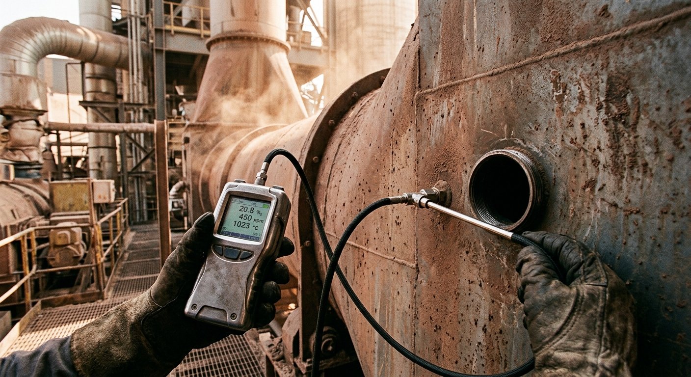
Wie wird Falschluft in einem Zementdrehrohrofen gemessen?
Falschluft wird durch den Vergleich der O₂-Konzentration vor und nach jedem Ofenabschnitt gemessen. Die Formel, die Probenahmestellen sowie die Kriterien für das Bestehen der Prüfung.
Falschluft in einem Zementdrehrohrofen wird durch den Vergleich der Sauerstoffkonzentration (O₂) an zwei Messpunkten entlang des Gaswegs bestimmt: Der Anstieg des O₂-Gehalts zwischen dem stromaufwärts und stromabwärts gelegenen Messpunkt quantifiziert die in diesem Bereich eingedrungene Falschluft. Dieses Verfahren basiert auf einer Sauerstoff-Massenbilanz und ist die einzige in der industriellen Ofenprüfung anerkannte quantitative Methode.
Der folgende Abschnitt erläutert die Formel, die Wahl der Messpunkte, die Bewertung der Ergebnisse sowie häufige praktische Fragen, die sich Anlageningenieure bei der Prüfung ihrer eigenen Öfen stellen. Es wird vorausgesetzt, dass Sie bereits den Artikel Falschluft in Zementdrehrohröfen gelesen haben; dieser definiert den Begriff Falschluft und erläutert dessen Bedeutung.
Die Standardmethode: Sauerstoffbilanz
O₂ ist der geeignete Indikator, da prozessbedingte Gase im Ofen keinen Sauerstoff enthalten. CO₂ aus der Entsäuerung des Kalksteins, CO₂ und H₂O aus der Brennstoffverbrennung sowie Spurengase wie SO₂ / NOₓ führen zu einer stöchiometrischen Verringerung des O₂-Gehalts der kontrollierten Verbrennungsluft. Jeder O₂-Anteil, der über dem Basiswert der kontrollierten Verbrennungsluft liegt, muss daher durch unbeabsichtigte Öffnungen (Falschluft) eingedrungen sein.
Die Zwei-Punkt-Methode ist der kanonische Ansatz in der industriellen Ausbildung und bei Audits. Der Anwender nimmt simultane O₂-Messungen an den stromaufwärts und stromabwärts gelegenen Messpunkten vor, die den zu prüfenden Abschnitt begrenzen, und wendet die im nächsten Abschnitt beschriebene Formel an. Sowohl der Holderbank Cement Course (das Standard-Schulungsprogramm für Anlagentechnik von Holcim) als auch der deutsche VDZ (Verein Deutscher Zementwerke) veröffentlichen diese Konvention; beide sind die Referenzen, die den meisten Zementwerksingenieuren geläufig sind.
Falschluft: Luft, die durch unbeabsichtigte Öffnungen (Dichtungen, Übergänge an der Einlaufkammer, Inspektionsöffnungen, Übergänge zwischen Kühler und Ofen) in ein Drehrohrofensystem eingesaugt wird, anstatt über den kontrollierten Verbrennungsluftpfad zuzuströmen. Die Quantifizierung erfolgt als Prozentsatz des gesamten Gasstroms am stromabwärts gelegenen Messpunkt.
Drei Instrumententypen sind im täglichen Einsatz:
- Zirkondioxid-Sonden (ZrO₂) für die kontinuierliche In-situ-Überwachung, typischerweise fest installiert am Vorwärmerauslass und Ofeneinlauf.
- Paramagnetische O₂-Analysatoren für mobile Messungen / Audits; dies ist die Mindestausstattung für eine einmalige Falschluftmessung.
- Extraktive Probenahmesysteme für heiße oder staubbeladene Schnittstellen, an denen eine Sonde verschmutzen würde; die Probe wird gekühlt, getrocknet und stromabwärts analysiert.
Die Formel
Der Falschluftanteil in einem Ofenabschnitt wird aus den O₂-Messwerten stromaufwärts und stromabwärts mittels einer Massenbilanzgleichung berechnet:
Falschluft % = ((O2_aus − O2_ein) / (20,9 − O2_aus)) × 100
Wobei:
- O2_ein: Sauerstoffkonzentration (% v/v, trocken) am stromaufwärts gelegenen Messpunkt
- O2_aus: Sauerstoffkonzentration (% v/v, trocken) am stromabwärts gelegenen Messpunkt
- 20,9: Sauerstoffkonzentration der Umgebungsluft (% v/v)
Berechnungsbeispiel: Angenommen, der O2_ein am Ofeneinlauf beträgt 3,0 % (ein typischer Basiswert für einen gut eingestellten modernen Trockenofen gemäß Cembureau Activity Report) und der O2_aus am Vorwärmerauslass beträgt 5,5 %. Dann ergibt sich:
Falschluft % = ((5,5 − 3,0) / (20,9 − 5,5)) × 100
             = (2,5 / 15,4) × 100
             = 16,2 %
Interpretation: 16,2 % des Gasstroms am Vorwärmerauslass sind durch Falschluftöffnungen zwischen den beiden Messpunkten eingedrungen – ein Wert, der im oberen Bereich liegt und eine Untersuchung rechtfertigt.
Hinweis zur Konvention: Einige Referenzen verwenden 20,95 % statt 20,9 % als O₂-Wert der Umgebungsluft. Der Unterschied beruht auf Rundungen; wählen Sie eine Konvention und wenden Sie diese konsistent bei allen Audit-Messungen in einem Werk an.
Wahl der Messpunkte
Falschluft wird abschnittsweise gemessen, nicht als ein einzelner globaler Wert. Die Standardabfolge der Messpunkte an einer modernen Anlage mit Vorwärmer, Kalzinator und Ofen ist:
- Ofeneinlaufkammer (Übergang Kühler zu Ofen): erfasst Leckagen an der Kühlerseite und der Einlaufdichtung
- Ofeneinlauf (Steigrohr oder Einlaufkammer): erfasst Leckagen an der Einlaufdichtung und der Einlaufkammer
- Jede Zyklonstufe des Vorwärmers (oben, mitte, unten): isoliert Leckagen pro Zyklonstufe und Rohrleitung
- Kalzinatorein- und -auslass (falls vorhanden): isoliert das Kalzinatorgehäuse
- Saugzugventilator-Einlass: der kumulative Endpunkt; der Messwert hier entspricht der gesamten Falschluftmenge, die der Ventilator fördern muss.
Die abschnittsweise Messung ermöglicht es dem Betreiber, den gesamten Falschluftanteil spezifischen Schnittstellen und damit bestimmten Ofeneinlaufdichtungen, Ofenauslaufdichtungen oder feuerfesten Verbindungen zuzuordnen. Ein einzelner globaler Messwert am Saugzugventilator zeigt zwar das Ausmaß des Problems, aber nicht den Ort der Fehlerbehebung.
Zwei praktische Disziplinen sind wichtig. Erstens die Korrektur auf Trockenbasis: O₂-Analysatoren messen auf Trockenbasis, daher müssen extraktive Proben vor der Messung getrocknet werden. Zweitens ist bei staubhaltigen Gasen eine isokinetische Probenahme erforderlich; eine falsch ausgerichtete Sonde führt in partikelreichen Strömen zu zu niedrigen O₂-Werten. Werke, die routinemäßige Audits durchführen, investieren in ein kalibriertes Probenahme-Kit; der Artikel Methodik für Falschluft-Audits beschreibt das vollständige Verfahren.
Was gilt als "akzeptabel"?
Industrielle Benchmarks setzen akzeptable Falschluftwerte für den Bereich vom Ofen bis zum Vorwärmer in einem gut abgedichteten modernen Trockenofen bei unter 8–10 % an. Werte über 15–20 % deuten auf defekte Dichtungen, Schäden an der Einlaufkammer oder Verschleiß an feuerfesten Verbindungen hin und erfordern sofortiges Handeln.
| Abschnitt | "Guter" Bereich (% Falschluft) | "Handlungsbedarf" |
|---|---|---|
| Ofeneinlaufkammer + Ofeneinlauf | < 5–8 % kombiniert | > 15 % |
| Vorwärmer (pro Stufe) | < 1–2 % pro Stufe | > 3 % pro Stufe |
| Gesamt Ofen bis Saugzugventilator | < 8–10 % | > 20 % |
Konventionen gemäß VDZ / Holderbank Ofen-Audit-Leitfaden. Der "gute" Bereich variiert je nach Ofenalter, Prozesstyp und Historie der Dichtungsmodernisierungen. Nassverfahren und ältere Halbtrockenöfen arbeiten mit höheren Basiswerten, als die obige Tabelle impliziert.
Bei Nachrüstungen, die von Oswal auditiert wurden, macht die Leckage an der Ofeneinlaufkammer vor einer Abdichtungsmaßnahme typischerweise 30–50 % des gesamten Falschluftwerts auf der Ofenseite aus. Dieses Verhältnis ist der Grund, warum die Abdichtung im Bereich der Einlaufkammer die erste Maßnahme mit dem höchsten ROI in den meisten Werken ist und der Ausgangspunkt für das integrierte Falschluft-Kontrollsystem. Der Zusammenhang mit den Brennstoffkosten ergibt sich aus dem spezifischen Brennstoffverbrauch: Jeder Prozentpunkt Falschluft über dem Basiswert führt zu einem messbaren Anstieg des kcal/kg-Werts beim spezifischen Brennstoffverbrauch.
Common questions about this topic
Vierteljährliche Intervalle bilden den Industriestandard für Öfen im stabilen Betrieb; zusätzliche Messungen sind nach jedem Dichtungswechsel, jeder feuerfesten Kampagne oder bei festgestellten Änderungen der Leistungsaufnahme des Saugzuggebläses erforderlich. Die meisten Anlagen stimmen das Audit zur Falschluftmessung auf den allgemeinen Turnus der Ofenleistungsüberprüfung ab. Das Engineering-Consulting-Team von Oswal führt in der Regel vierteljährlich bis halbjährlich ein vollständiges Falschluft-Audit in Verbindung mit einer SFC-Überprüfung durch, abhängig vom Alter der Anlage.
Ein handgeführter paramagnetischer O₂-Analysator ist die erforderliche Mindestausstattung; ohne O₂-Messwerte an zwei Punkten entlang des Gaswegs ist keine präzise Falschluftmessung möglich. Eine visuelle Dichtungsprüfung identifiziert starke Leckagen (man kann oft sehen und hören, wie Luft in eine beschädigte Einlassdichtung gesaugt wird), quantifiziert diese jedoch nicht, und eine rein qualitative Prüfung allein ist ein unzureichender Nachweis für einen Business Case zur Nachrüstung.
Der Messwert am Ofeneinlauf erfasst nur die ofenseitige Falschluft: Ofenkopf, Einlaufdichtung und Einlaufgehäuse. Der Messwert am Saugzuggebläse erfasst die kumulierte Falschluft bis zum Gebläse, einschließlich jeder Vorwärmerstufe. Die Falschluft am Saugzug ist typischerweise 2-3-mal höher als der Wert am Ofeneinlauf, da der Vorwärmer zusätzlich zum ofenseitigen Wert seine eigene stufenbezogene Falschluft beisteuert.
Sources
- Holderbank Group / Holcim, *Cement Manufacturing: Process Technology*, Volume 2 (Holderbank Cement Course training corpus). The canonical training reference for the false-air O₂ balance formula across the cement industry.
- Verein Deutscher Zementwerke (VDZ), *VDZ Activity Report* (annual). German cement industry association; publishes the kiln-audit and false-air benchmark conventions used in this piece
- European Cement Research Academy (ECRA)
- Cembureau, *Activity Report 2023*. European cement industry baseline figures, including dry-process kiln O₂ ranges
- ABB and Siemens application notes on continuous O₂ measurement in cement plants (references for the instrument types listed above). --- *Auditing false air on a specific kiln configuration is one of the engineering-consulting team's standard scopes. If you're sizing a retrofit case or commissioning a baseline measurement campaign, the [engineering-consulting service](/en/services/engineering-consulting) walks the methodology above on-site.*
Verwandte Artikel
Discuss Your Sealing Requirements
Our engineering team can help identify the right sealing solution for your application.
Contact Engineering Team“Überall dort, wo Hochtemperatur-Drehrohröfen unter kontrollierter Atmosphäre betrieben werden, sorgen Oswal-Dichtungssysteme für Energieeffizienz und Prozessstabilität.”