Waste Management Kiln Sealing: Incinerator Guide
Gestione rifiuti e ambientale
A rotary kiln incinerator or waste-to-energy plant needs a kiln seal that controls air ingress at the feed and discharge ends while withstanding extreme, variable temperatures and a corrosive, particulate-laden flue gas. In waste management the seal does double duty: it protects the controlled-combustion conditions that destroy hazardous compounds, and it limits uncontrolled air that disturbs the draft balance and the emissions profile. Unlike a cement kiln, a hazardous waste incinerator runs a deliberately oxidising, high-excess-air combustion, but seal leakage still matters because it shifts draft, dilutes flue gas, and undermines the temperature and residence time on which destruction efficiency depends.
The waste management industry use case for kiln sealing
In a waste-to-energy or incineration plant, the kiln seal supports both regulatory destruction performance and stable energy recovery. A rotary kiln incinerator exposes mixed waste to temperatures that can exceed 1,200°C, and the downstream secondary combustion chamber holds roughly 1,000-1,200°C for a minimum residence time of about two seconds to complete the destruction of CO, dioxins, and furans [1]. Uncontrolled air ingress at the kiln seals disturbs the draft and temperature balance that those conditions rely on, so sealing is part of the combustion-control system, not a peripheral fitting.
The seal also governs dust and emissions containment at the kiln interfaces. Leakage paths at the feed and discharge ends let particulate and flue gas escape and pull in tramp air that the ID fan must then handle, raising fan load on a plant that already runs high excess air. The waste-to-energy plant universe is large and growing across municipal solid waste, hazardous waste, and medical waste streams; for the process context, see waste-to-energy plants, hazardous waste incineration, and the kiln-specific detail in rotary kiln incinerators.
The kiln process chain in a rotary kiln incinerator
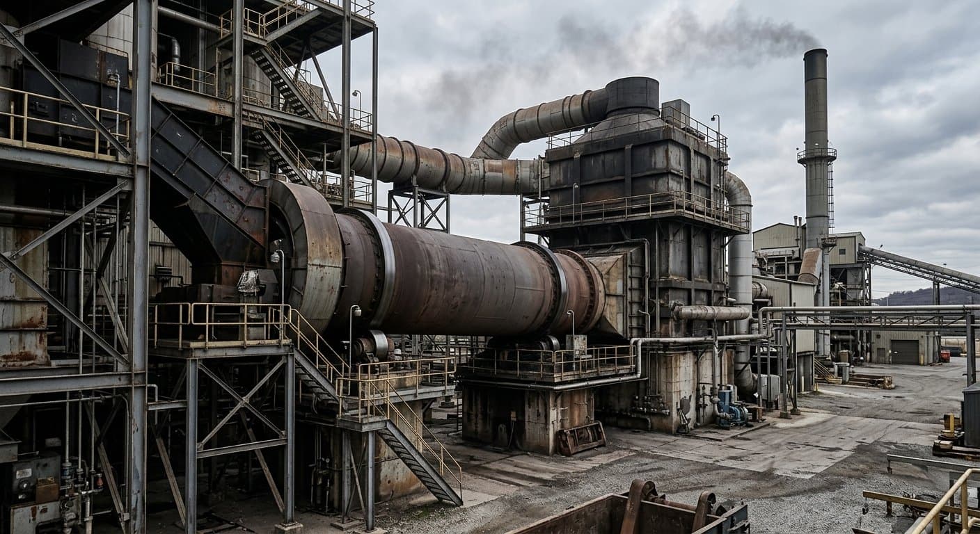
The waste incineration kiln chain feeds mixed solid and liquid waste into a slowly rotating kiln where it dries, gasifies, and combusts, then passes the flue gas to a secondary combustion chamber and a heat-recovery train, with the seals guarding the feed and discharge interfaces of the rotating kiln.
| Stage | Function | Approximate temperature |
|---|---|---|
| Rotary kiln (primary) | Waste dried, gasified, and combusted; ash separated | 900-1,200°C [1] |
| Secondary combustion chamber | Remaining volatiles, CO, dioxins, furans destroyed; ~2 s residence | 1,000-1,200°C, ≥2 s [1] |
| Heat recovery / boiler | Flue-gas heat recovered for steam and power (WTE) | falling from ~1,000°C |
| Flue-gas cleaning | Particulate, acid gas, and pollutant removal before stack | cooled |
The kiln seal sits at the feed end, where heterogeneous waste enters, and at the discharge end, where ash drops out and flue gas passes to the secondary chamber. Both interfaces are under the plant's induced draft, so any gap pulls tramp air into the system. Because the waste feed is heterogeneous and intermittent, the kiln runs a wider and more variable temperature swing than a cement or lime kiln, which loads the seal with frequent thermal cycling on top of the high peak temperature. A municipal solid waste incinerator, a solid waste incinerator, and a dedicated hazardous waste rotary kiln share this chain, differing mainly in feed and flue-gas-cleaning requirements.
Sealing requirements specific to waste management: temperature, atmosphere, dust profile
Waste management kiln sealing requirements are defined by extreme and highly variable temperature, an oxidising high-excess-air combustion, and a corrosive, abrasive, chemically mixed dust and flue-gas load. The corrosion and thermal-cycling exposure here is harsher and less predictable than in cement, lime, or alumina.
False air (incineration): uncontrolled atmospheric air entering the kiln through worn seals or interface gaps rather than the metered combustion-air path. It disturbs the draft and temperature balance, dilutes the flue gas, raises ID fan load, and can compromise the temperature and residence time needed for complete destruction.
The governing conditions:
- Temperature. Peaks above 1,200°C with wide swings driven by heterogeneous waste, so graphite-based sealing elements and strong thermal-shock tolerance are required. The cycling, not just the peak, drives wear.
- Atmosphere. Oxidising, high excess air; the sealing target is stable draft control and emissions containment rather than zero oxygen ingress, but uncontrolled air still undermines destruction performance.
- Dust and corrosion. Mixed waste produces abrasive ash plus corrosive species (chlorides, sulphur, alkalis), so seal materials face both mechanical abrasion and chemical attack. Abrasion-resistant construction and a controlled contact-pressure mechanism are essential.
- Movement. Standard rotary-kiln radial expansion and axial float, with the added complication of variable thermal expansion as the load changes.
The trade-off is the usual lamella-versus-graphite balance, sharpened by the thermal cycling: a seal here must both follow large, frequent movement and survive corrosive high-temperature exposure, which points to a hybrid assembly for most incineration kilns.
Recommended Oswal products for waste management
For rotary kiln incinerators and waste-to-energy kilns the primary match is the Duplex Kiln Sealing System, whose hybrid lamella-plus-graphite design combines the movement compensation needed for variable thermal cycling with the high-temperature durability needed for peak combustion [2]. The feed and discharge interfaces are covered by the Kiln Inlet Sealing System and the Kiln Outlet Sealing System, the latter built for abrasion resistance and thermal-shock tolerance under heavy ash load. Component-level, the Graphite-Based Sealing Elements handle the high-temperature zone, the High-Temperature Radial Seals maintain circumferential contact, and the Axial Compensation Seals absorb kiln float. Where draft and emissions containment are managed across the whole kiln, the Integrated False Air Control programme covers the feed, discharge, and hood interfaces as a system.
Waste management industry application examples
In rotary kiln incinerators we have assessed, the combination of corrosive flue gas and wide thermal cycling makes seal-face degradation faster and less predictable than in single-feedstock kilns. A typical pattern: a hazardous waste kiln handling a variable chloride-bearing feed sees its discharge-end seal attacked by both abrasion and acid-gas corrosion, so the contact face loses integrity sooner than the same seal would on a steady oxidising process. A higher-durability graphite-and-lamella assembly holds the seal through more thermal cycles before replacement.
A second recurring case is draft disturbance from feed-end leakage. Because the secondary combustion chamber depends on stable temperature and the two-second residence time, air ingress at the kiln feed that pulls the draft off-balance can ripple downstream into destruction performance; operators tuning for stable burnout often find the cause at the seal rather than in the burner controls. A third pattern, common in municipal solid waste and solid waste incinerators, is rising ID fan load traced to accumulated tramp air across worn interfaces, where consolidating the sealing improves both fan power and emissions stability. For the regulatory framing, see hazardous waste incineration.
Prodotti consigliati
Soluzioni Oswal per Gestione rifiuti e ambientale
Controllo integrato falsa aria
Protezione dell'energia attraverso l'ingegneria della sigillatura di precisione
Sistema di tenuta uscita forno
Prestazioni di temperatura estreme nella zona di scarico del clinker
Tenuta in grafite
Durabilità termica per interfacce Kiln ad alta temperatura
Fonti
- Rotary kiln incinerator references (WikiWaste / ScienceDirect / Igniss), *Primary kiln and secondary combustion chamber temperatures and residence time for hazardous waste destruction*, 2023-2024. https://wikiwaste.org.uk/index.php/Rotary_Kiln and https://www.sciencedirect.com/topics/engineering/rotary-kiln-incinerator
- Oswal Industries, *OSWAL Kiln Seals product catalogue* and *Duplex Kiln Sealing System catalogue*, 2024 (product specifications and configuration).
Domande frequenti
Domande comuni sulla sigillatura del forno nell'industria.
Le prestazioni della tenuta del forno influenzano la stabilità dell'atmosfera di combustione, che a sua volta incide sull'efficienza di distruzione nelle applicazioni per rifiuti pericolosi e sulla completezza della combustione nelle applicazioni WTE (Waste-to-Energy). Un'atmosfera stabile all'interno del forno è un prerequisito fondamentale per soddisfare gli standard normativi di efficienza di distruzione (tipicamente pari o superiore al 99,99%) e per garantire il funzionamento stabile delle apparecheature a valle per il controllo dell'inquinamento atmosferico.
Sì. I sistemi di tenuta Oswal sono configurati per applicazioni di incenerimento di rifiuti pericolosi con specifiche dei materiali adeguate alla temperatura operativa, alla composizione dei gas e al profilo di corrosività. Il servizio di consulenza ingegneristica e audit identifica la configurazione di tenuta specifica per ogni impianto; per la maggior parte delle applicazioni si utilizzano configurazioni standard in Duplex, con varianti esclusivamente in grafite laddove richiesto dalla composizione chimica dei fumi.
Le tenute dei forni WTE utilizzano tipicamente la configurazione Oswal Duplex con componenti strutturali in acciaio al carbonio ed elementi di tenuta in grafite specificati per un intervallo di temperatura operativa di 850-950 °C. I gradi dei materiali vengono adeguati verso l'alto per gli impianti che bruciano flussi di rifiuti a temperature più elevate o per impianti con fumi particolarmente corrosivi (rifiuti clorurati o solforati).
Gestione rifiuti e ambientale Indagine sulla chiusura
Condividi la configurazione del forno e le condizioni operative con il nostro team di ingegneri.
Richiedi un preventivo“Ovunque i forni rotanti ad alta temperatura operino in atmosfera controllata, i sistemi di tenuta Oswal garantiscono efficienza energetica e stabilità di processo.”