
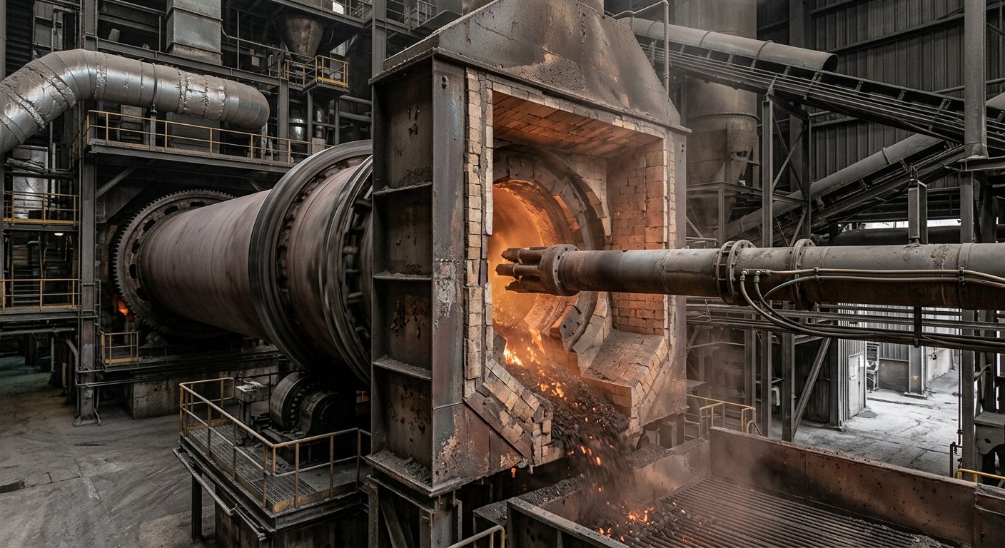
Die Ofenhaube: Konfigurationen der Ein- und Auslasshauben
Die Ofenhaube umschließt beide Enden eines Drehrohrofens, leitet den Gasstrom und dichtet gegen den Ofenmantel ab. Einlass- vs. Auslasskonfigurationen, Abdichtung und Falschluft.
Die Ofeneinlauf- bzw. Ofenauslaufkammer ist das stationäre, feuerfest ausgekleidete Stahlgehäuse an jedem Ende eines Drehrohrofens. Sie leitet den Gasstrom, schirmt die Strahlung der Brennzone ab, nimmt am Auslaufende den Hauptbrenner auf und bildet die mechanische Schnittstelle zwischen dem rotierenden Ofenrohr und der fest installierten Anlagenverrohrung. Jeder Drehrohrofen verfügt über zwei dieser Kammern: eine Einlaufkammer auf der Aufgabeseite (Vorwärmer) und eine Auslaufkammer auf der Austragsseite (Kühler).
Dieser Artikel behandelt die Funktion der jeweiligen Kammer, die in der Praxis anzutreffenden Konfigurationen und erläutert, warum der Spalt zwischen Kammer und Ofenrohr eine der größten Falschluftquellen in einem Zementwerk darstellt. Der Begriff „Ofenkammer“ bezieht sich hier auf die 5–15 m großen industriellen Stahlkonstruktionen in Zement-, Kalk-, DRI- und Kalzinieranlagen, nicht auf die gleichnamige Komponente in der Töpferkunst.
Ofenkammer: Das stationäre, feuerfest ausgekleidete Gehäuse am Einlaufende (Einlaufkammer) und Auslaufende (Auslaufkammer) eines Drehrohrofens. Sie leitet den Gasstrom, schirmt die Strahlung der Brennzone ab, nimmt den Hauptbrenner auf und bildet über eine Kammerdichtung die Schnittstelle zur festen Anlagenverrohrung.
Einlaufkammer vs. Auslaufkammer: Was ist der Unterschied?
Die Einlaufkammer befindet sich am Aufgabende bei Gastemperaturen von etwa 1.000–1.100 °C und ist mit dem Steigrohr oder Vorwärmer verbunden. Die Auslaufkammer befindet sich am Austragsende, ist der 1.300–1.500 °C heißen Strahlung der Brennzone ausgesetzt, ist mit dem Klinkerkühler verbunden und nimmt den Hauptbrenner auf. Die Temperaturdifferenz erfordert unterschiedliche Auslegungen bei Feuerfestmaterial und Abdichtung: Die Einlaufkammer steuert den vorgelagerten Zug und die Gasstromrichtung; die Auslaufkammer gewährleistet die Brennerstabilität, den Klinkeraustrag und (in Anlagen mit Vorcalcinator) die Tertiärluftentnahme zum Calcinator.
| Merkmal | Einlaufkammer | Auslaufkammer |
|---|---|---|
| Ofenende | Aufgabeseite (vorgelagert) | Austragsseite (nachgelagert) |
| Typische Gas-/Strahlungstemperatur | 1.000–1.100 °C (Holderbank Cement Course, Vol 2) | 1.300–1.500 °C (Holderbank Cement Course, Vol 2) |
| Verbindung zu | Steigrohr / Vorwärmer | Klinkerkühler |
| Brenneraufnahme? | Nein | Ja (in Zement- und den meisten Kalzinieröfen) |
| Tertiärluftentnahme (Vorcalcinator) | Nein | Ja |
| Feuerfestmaterial | Hochtonerde- oder basische Steine | Verschleißfest + hochtemperaturfest im Bereich der Brennerflamme |
| Hauptursachen für Falschluft | Einlaufkammerdichtung, Inspektionsöffnungen, Kompensatoren am Steigrohr | Auslaufkammerdichtung, Übergang Kühler-zu-Kammer, Brennerrohrdurchführung |
Die Abdichtung der Einlaufkammer und der Auslaufkammer stellt keine identische Aufgabenstellung dar. Eine Auslaufkammerdichtung ist höheren Dauertemperaturen und einer stärkeren Staubbelastung ausgesetzt; eine Einlaufkammerdichtung ist zwar geringeren Temperaturen ausgesetzt, unterliegt jedoch bei Stillständen stärkeren thermischen Wechselbeanspruchungen.
Konfigurationen der Ofenkammern
Die Geometrie der Ofenkammer wird durch die Brenneranordnung, die Tertiärluftentnahme und die Ausrichtung zwischen Ofen und Vorwärmer bestimmt. Fünf Konfigurationen decken nahezu alle in der Praxis vorkommenden Fälle ab.
Auslaufkammer:
- Gerade Ein-Brenner-Kammer. Brenner fluchtend zur Ofenachse. Der Standard für Zement-Trockenverfahren und die meisten Kalköfen.
- Abgewinkelte Kammer. Brenner versetzt, um Flammenberührung zu vermeiden oder Platz für Lanzen zur Sekundärbrennstoffinjektion zu schaffen.
- Mehrbrenner-Kammer. Hauptbrennstoffbrenner plus Sekundärbrennstoff- und Zündbrenner, üblich in Mitverbrennungsanlagen; die Kammer ist verbreitert, um das Brenner-Array aufzunehmen.
Einlaufkammer:
- Gerade Einlaufkammer. Ofenachse fluchtend mit dem Steigrohr. Sauberster Gasstrom, geringster Druckverlust.
- Versetzte Einlaufkammer. Ofenachse seitlich zum Steigrohr versetzt; ein gekrümmter Übergang leitet das Gas um. Druckverlust und Staubablagerungen sind höher; der Versatz muss so konstruiert sein, dass Staubansammlungen vermieden werden.
In Zementwerken mit Vorcalcinator beherbergt die Auslaufkammer zudem die Tertiärluftentnahme zum Calcinator, sodass jede Nachrüstung der Brenneranordnung auch eine Anpassung der Tertiärluftverrohrung als gekoppelte Änderung erfordert.
Wo die Ofenkammer auf das Ofenrohr trifft: Das Dichtungsproblem
Der Spalt zwischen dem rotierenden Ofenrohr und der stationären Kammer ist eine der größten Falschluftquellen in einem Zementwerk. Unbehandelt macht die Leckage im Kammerbereich typischerweise 30–50 % der gesamten Falschluft auf der Ofenseite aus; eine gut abgedichtete Kammer hält die gesamte Verbrennungsluftleckage unter 5 %, während eine beschädigte Dichtung diesen Wert auf über 20 % ansteigen lassen kann [2][3].
Der Spalt existiert, weil sich der Ofen bewegt, die Kammer jedoch nicht. Drei Arten der Relativbewegung müssen von der Dichtung ausgeglichen werden:
- Axiale thermische Ausdehnung. Zementofenrohre sind für eine Längenausdehnung von etwa 0,25–0,3 % zwischen Kaltstart und stationärem Betrieb ausgelegt; bei einem 60–70 m langen Ofen entspricht dies etwa 100–200 mm axialer Ausdehnung (Konstruktionsrichtlinien von Phillips Kiln Services / cementkilns.co.uk) [1].
- Radialer Schlag und Unrundheit des Ofenrohrs. Eine Unrundheit des Ofenrohrs von 0,5–1 % des Durchmessers ist normal; bei einem 5 m Ofenrohr entspricht dies einer radialen Abweichung von 25–50 mm pro Umdrehung.
- Vibrationen. Schwingungen von der Antriebsseite und Lastverlagerungen überlagern die langsame thermische Bewegung und die Unrundheit mit einer hochfrequenten Komponente.
Die Dichtung muss zudem Staubeintritt, Abplatzungen des Feuerfestmaterials an der Kammerkante und thermische Wechselbeanspruchungen bei jedem Stillstand tolerieren. Die Produktliteratur von Oswal bringt es auf den Punkt: „Herkömmliche Dichtungssysteme sind für statische Bedingungen ausgelegt, während Drehrohröfen unter ständiger axialer Bewegung, thermischer Ausdehnung, Unrundheit und mechanischer Verformung arbeiten“ [4]. Für Anlagen, die die Falschluft im Kammerbereich in letzter Zeit nicht gemessen haben, erläutert der Artikel wie Falschluft in einem Zementofen gemessen wird die O₂-Bilanzmethode, und Falschluft in Zementöfen verstehen erklärt, warum der prozentuale Anteil für die Brennstoffkosten entscheidend ist.
Dichtungstechnologien für Ofenkammern
Drei Dichtungstechnologien dominieren bei Ofenkammeranwendungen: Lamellendichtungen für mechanische Bewegungen, Graphitdichtungen für thermischen Kontakt und hybride Duplex-Systeme, die beides kombinieren. Die meisten Installationen trennen zudem den radialen und axialen Ausgleich in dedizierte Elemente innerhalb einer Baugruppe.
| Dichtungstyp | Temperaturgrenze | Bewegungstoleranz | Staubverträglichkeit | Toleranz gegenüber thermischen Wechseln | Typische Nachrüstkomplexität |
|---|---|---|---|---|---|
| Lamelle | ~600 °C dauerhaft | Hoch (axial + radial) | Gut | Exzellent | Niedrig bis mittel |
| Graphit | ~1.000 °C dauerhaft | Mittel | Mittel | Empfindlich bei schnellen Wechseln | Mittel |
| Duplex-Hybrid (Lamelle + Graphit) | ~1.000 °C dauerhaft | Hoch | Gut | Gut | Mittel bis hoch |
Bereiche gemäß Oswal-Produktspezifikationen [4][5]. Spezifische Grenzwerte hängen von der Dichtungsauslegung und dem Betriebsbereich des Ofens ab.
Lamellendichtungen. Mehrblättrige, überlappende Stahlsegmente, die federbelastet gegen das rotierende Ofenrohr drücken. Jedes Blatt federt unabhängig, sodass axiale und radiale Bewegungen gut ausgeglichen werden. Die Produktlinie der lamellenbasierten Dichtungselemente ist die typische Wahl für Einlaufkammern und für Auslaufkammern, bei denen die gasseitige Temperatur unter dem Dauerlimit des Lamellenmaterials bleibt.
Graphitdichtungen. Segmentierte Graphitblöcke, die durch Gegendruck gegen das Ofenrohr gehalten werden. Graphit bewältigt Dauertemperaturen besser als Stahl, ist jedoch empfindlich gegenüber schnellen thermischen Wechseln; die Blöcke können bei Stoßbelastung reißen. Die Produktlinie der graphitbasierten Dichtungselemente eignet sich für Strahlungsumgebungen in Auslaufkammern, die über das hinausgehen, was eine Lamellendichtung aushält.
Duplex-Hybrid. Das Oswal Duplex-Ofendichtungssystem kombiniert eine primäre Lamellenschnittstelle (zur Aufnahme axialer und radialer Bewegungen) mit einer sekundären Graphitschnittstelle (zur Aufrechterhaltung der thermischen Dichtheit) in einer Baugruppe [4]. Es wurde für Öfen mit hoher Unrundheit oder häufigen thermischen Wechseln entwickelt – Bedingungen, unter denen eine Dichtung mit nur einer Technologie zeitweise den Kontakt verliert und undicht wird.
Auf Systemebene bündeln die Produktlinien Ofeneinlauf-Dichtungssystem, Ofenauslauf-Dichtungssystem und integrierte Falschluftkontrolle die Abdichtung im Kammerbereich mit Überwachungs- und Nachrüstungsoptionen. Der Duplex-Katalog von Oswal gibt eine Amortisationszeit von 6–18 Monaten für integrierte Nachrüstungen durch geringeren Brennstoffverbrauch und reduzierte Leistungsaufnahme des Saugzuggebläses an [4]; der tatsächliche Wert hängt in jeder Anlage vom Falschluft-Basiswert und den lokalen Brennstoffkosten ab.
Common questions about this topic
Die Einlaufhaube befindet sich am Aufgabeseite bei Gastemperaturen von etwa 1.000–1.100 °C und verbindet den Ofen mit dem Steigrohr des Vorwärmers. Die Auslaufhaube befindet sich am Austragsende, ist der Strahlungswärme von 1.300–1.500 °C aus der Sinterzone ausgesetzt, verbindet den Ofen mit dem Klinkerkühler und nimmt den Hauptbrenner auf. Das Ofeneinlauf-Dichtungssystem verwendet typischerweise Lamellenelemente; das Ofenauslauf-Dichtungssystem erfordert aufgrund der Strahlungsumgebung häufig Graphit- oder Hybridabdichtungen.
Bei einer unzureichend abgedichteten Haube macht die Schnittstelle der Haube typischerweise 30–50 % der gesamten Falschluft auf der Ofenseite aus, wobei die gesamte Leckage der Verbrennungsluft 20 % übersteigen kann. Eine gut abgedichtete Haube hält diesen Wert unter 5 %. Der Wert für ein spezifisches Werk muss direkt mittels der O₂-Bilanzmethode gemessen werden, die unter wie Falschluft gemessen wird beschrieben ist.
Der Austausch erfolgt basierend auf dem gemessenen Falschluftanteil und sichtbarem Verschleiß, nicht nach Kalenderzeit. Typische Intervalle liegen bei 12–24 Monaten für Lamellenelemente und 2–4 Jahren für Graphitelemente; bei Öfen mit hoher Ovalität oder Anlagen mit häufigen thermischen Wechselbeanspruchungen sind die Intervalle kürzer. Die meisten Betreiber koppeln die Dichtungsinspektion an die geplante feuerfeste Ausmauerungskampagne.
Sources
- Phillips Kiln Services / cementkilns.co.uk, *Cement Kilns: Design Features of Rotary Kilns* (industry-reference design conventions for kiln shell axial expansion of 0.25-0.3% of length)
- Verein Deutscher Zementwerke (VDZ), *VDZ Activity Report* (annual; kiln-audit and false-air benchmark conventions)
- Cembureau, *Activity Report 2023*. European cement industry baseline figures, including kiln gas-stream conventions used in false-air calculations
- Oswal Engineers, *Duplex Kiln Sealing System* (product catalogue, `KilnSeal_DuplexType_OK_CAT.pdf`)
- Oswal Engineers, *Kiln Sealing Systems* (product overview, `OSWAL_kilnseal.pdf`)
- Holderbank Group / Holcim, *Cement Manufacturing: Process Technology*, Volume 2 (Holderbank Cement Course training corpus; canonical industry reference for kiln-hood temperature ranges and pyroprocessing layout conventions).
- European Cement Research Academy (ECRA), kiln-process technical references. https://ecra-online.org/ --- *Hood-area false air is the highest-ROI first fix on most cement kilns. If you're scoping a hood-seal retrofit or running a baseline false-air audit, Oswal's [engineering-consulting service](/en/services/engineering-consulting) walks the inlet and outlet hood methodology described above on-site.*
Verwandte Artikel
Discuss Your Sealing Requirements
Our engineering team can help identify the right sealing solution for your application.
Contact Engineering Team“Überall dort, wo Hochtemperatur-Drehrohröfen unter kontrollierter Atmosphäre betrieben werden, sorgen Oswal-Dichtungssysteme für Energieeffizienz und Prozessstabilität.”