Rotary Kiln Incinerators: Design and Use Cases
Rotary kiln incinerators destroy hazardous waste in an inclined refractory-lined cylinder plus afterburner. Design parameters, modes, and sealing.
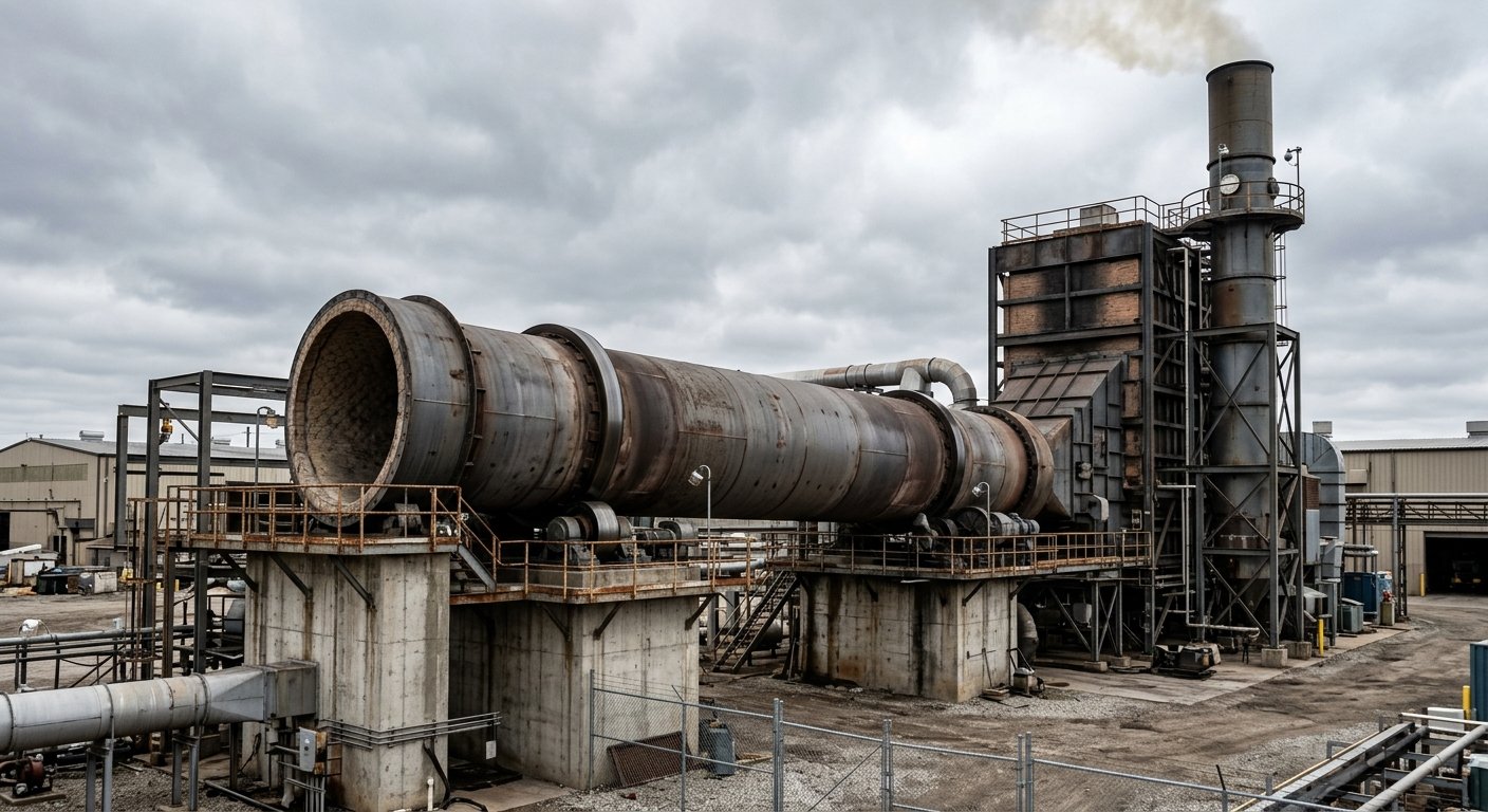
A rotary kiln incinerator is a slowly rotating, slightly inclined refractory-lined steel cylinder that thermally destroys solid, liquid, and sludge wastes, discharging combustion gases into a downstream secondary combustion chamber where destruction is completed. It is the workhorse of hazardous and medical waste treatment because one unit accepts waste streams in any physical state. This piece covers the design parameters, the slagging and ashing operating modes, the main use cases, and the kiln inlet/outlet sealing problem that governs combustion control and destruction efficiency.
Note one point of confusion first. "Rotary kiln" also names the process kilns used in cement, lime, and direct-reduced iron plants. This piece is about the incinerator configuration, where the goal is waste destruction rather than producing clinker or sponge iron. The sealing engineering at the kiln-to-hood interface, however, is common to both, which is where Oswal's products apply.
What is a rotary kiln incinerator?
A rotary kiln incinerator is a two-stage thermal-destruction system: a refractory-lined rotating cylinder (the kiln) that combusts and tumbles the waste, followed by a secondary combustion chamber (afterburner) that holds the flue gas at high temperature long enough to destroy the remaining organics. The rotation continuously exposes fresh waste surface to heat and oxygen, which gives more even burnout than a fixed-hearth design.
Rotary kiln incinerator: an inclined, refractory-lined rotating steel cylinder that thermally treats waste by tumbling it down a temperature gradient, paired with a downstream secondary combustion chamber that completes the destruction of combustion gases.
Secondary combustion chamber (afterburner): the chamber downstream of the kiln where flue gas is held above 1,100 C for more than 2 seconds to complete oxidation of residual organics and minimise products of incomplete combustion [1][2].
Rotary kiln incineration is regarded as Best Available Technology for hazardous and medical waste because continuous rotation creates near steady-state conditions that are easier to control than batch combustion [3].
How a rotary kiln incinerator is designed
The kiln is a refractory-lined steel cylinder with a length-to-diameter ratio of 2-8, inclined 1-5 degrees from horizontal and rotating at 0.2-5 rpm, so that waste tumbles down the slope while combustion gases pass forward to the afterburner [4]. Slope and rotational speed together set how long solids stay in the kiln, typically 30-90 minutes [4]. Higher length-to-diameter ratios and slower rotation are used for wastes that need a longer burn.
The refractory lining is both the kiln's protection and its main operating cost. It shields the steel shell from the flame and the molten or abrasive bed, and it is the component that degrades fastest, especially in high-temperature slagging service [5]. Refractory maintenance dominates the lifetime cost of a hazardous-waste kiln.
The numbers below are the parameters a process engineer sizes first.
| Parameter | Typical range | Note |
|---|---|---|
| Kiln length-to-diameter ratio (L/D) | 2-8 | Higher L/D for wastes needing longer residence [4] |
| Rotational speed | 0.2-5 rpm | Slower for longer burnout [4] |
| Slope (inclination) | 1-5 degrees | Sets solids transport with rotation [4] |
| Solids residence time in kiln | 30-90 minutes | Long residence decomposes halogenated organics [1][4] |
| Kiln operating temperature | 850-1,200 C | Ashing low end; slagging high end [2][6] |
| Secondary combustion chamber temperature | >1,100 C | Completes destruction of flue-gas organics [1][2] |
| Flue-gas residence in SCC | >2 seconds | Standard design basis for complete burnout [1][2] |
The kiln does the bulk combustion and the solids burnout; the afterburner guarantees the gas-phase destruction. Both stages matter, and both depend on holding the design temperature, which is exactly what air in-leakage undermines.
Co-current vs counter-current configuration
Co-current kilns move flue gas in the same direction as the waste; counter-current kilns move gas against the waste flow, which improves ash burnout but exposes the feed end to hotter gas. The choice changes which end of the kiln runs hottest, and that drives both refractory selection and the sealing specification at each hood.
In a counter-current kiln, incoming combustion air cools the exiting ash and ensures a complete burn-out: ash leaves with unburned carbon below 0.5% and no black colour, with little slagging tendency [7]. In a co-current kiln, the gas loses its oxygen to combustion as it travels with the waste, so it can exit with low oxygen (around 6%) at roughly 1,000 C; ash can leave with more than 2% unburned carbon and a higher slagging risk [7]. Counter-current designs generally give cleaner burnout; co-current designs are simpler to arrange for certain feed and gas-handling layouts.
Slagging vs ashing operating modes
Rotary kiln incinerators run in one of two thermal modes: ashing (non-slagging) at roughly 850-1,000 C, where the ash stays solid, or slagging at 1,100-1,400 C, where the ash melts into a vitrified slag [6]. The mode is a deliberate design choice, and it trades waste-residue quality against refractory life.
Slagging operation melts the ash into a glassy slag that encapsulates heavy metals, lowering the leachability of the final residue and making it safer to landfill [6]. The cost is refractory attack. High-alkali molten slag adheres to the hot face of the lining, infiltrates the brick, and drives spalling; it also builds slagging rings inside the kiln that disrupt material flow [5]. Ashing operation keeps the ash solid and is gentler on the lining, but the residue is less inert. The hotter the mode, the shorter the refractory wear interval.
| Mode | Temperature | Ash form | Refractory impact |
|---|---|---|---|
| Ashing (non-slagging) | 850-1,000 C | Solid ash | Lower wear [6] |
| Slagging | 1,100-1,400 C | Molten vitrified slag | Higher wear; slag infiltration and ring formation [5][6] |
What rotary kiln incinerators are used for
Rotary kiln incinerators handle the widest range of waste of any thermal-treatment technology: solid, liquid, and sludge streams that narrower incinerators cannot accept in one unit [3]. This flexibility is the reason they are the default choice for mixed and hazardous feeds.
Typical applications:
- Hazardous industrial waste: chemical solvents, oily residues, off-specification process streams.
- Medical and clinical waste: the continuous, high-temperature destruction this category requires [3].
- Contaminated soil: thermal desorption and destruction of organics in remediation projects.
- Industrial and sewage sludges: including heavy-metal-rich sludges from wastewater treatment.
- Persistent organic pollutants (POPs): PCBs, dioxin-bearing wastes, and other halogenated organics that demand the longest residence and highest temperatures.
The regulatory bar for hazardous-waste destruction is set by destruction and removal efficiency. Under US EPA RCRA rules (40 CFR 264.343), a hazardous-waste incinerator must achieve a minimum 99.99% DRE for each principal organic hazardous constituent in its permit, and 99.9999% (so-called six nines) for dioxin-listed wastes such as F020-F023, F026, and F027 [8]. Modern rotary kiln incinerators routinely exceed the 99.99% threshold [2].
Destruction and removal efficiency (DRE): the fraction of a designated hazardous organic constituent destroyed or removed, expressed as a percentage. A DRE of 99.9999% means one molecule of the constituent is emitted for every million entering the incinerator [8].
For the broader regulatory and process framing of this vertical, see the companion pieces on hazardous waste incineration and waste-to-energy plants.
The kiln inlet/outlet sealing challenge
The seal at the rotary kiln incinerator's inlet and outlet hoods controls false air, the uncontrolled air in-leakage drawn into the kiln through the gap between the rotating shell and the stationary hood. Excess false air destabilises combustion control, cools the kiln below its target temperature, and undermines destruction efficiency, all of which directly threaten the DRE the plant is permitted against.
False air: air drawn into a kiln system through unintended openings (seals, hood interfaces, inspection ports) rather than through the controlled combustion-air path. It is parasitic: every cubic metre must be heated to process temperature, and it dilutes and cools the combustion zone.
The mechanics are the same as in a false air problem on a cement kiln, with three conditions that make the incinerator seal harder. First, the seal must tolerate the thermal expansion and axial movement of a shell that swings through a wide temperature range. Second, it sits in a stream of abrasive ash and, in slagging service, sticky slag particles. Third, the flue gas is corrosive: acid gases and chlorides from halogenated wastes attack sealing materials that a cement kiln never sees. A seal that holds on a clean cement kiln can fail quickly on a chlorinated-waste incinerator.
This is why incinerator hoods are sealed with movement-tolerant, corrosion- and abrasion-resistant elements rather than a rigid plate. Lamella sealing elements flex to follow shell movement and ovality; graphite sealing elements provide durability and self-lubricating wear resistance in the high-temperature zone; and axial compensation seals absorb the kiln's thermal growth without losing contact force.
How Oswal's kiln seals apply to waste incinerators
The kiln-to-hood interface on a waste incinerator presents the same engineering problem as on a cement or DRI kiln: a rotating, thermally expanding shell sealing against a stationary hood under dust and corrosive gas. Oswal designs and manufactures the seal assemblies for both ends of that interface.
The kiln inlet sealing system controls air ingress at the feed end, where stable combustion conditions depend on a predictable air path. The kiln outlet sealing system handles the discharge-end hood, one of the harshest thermal and abrasive positions in the plant. For incinerators where a single barrier is not sufficient for the duty, the duplex kiln sealing system combines lamella flexibility with graphite durability, providing a primary and a secondary sealing barrier at the same position so atmosphere control holds even as the primary element wears.
Seal specification for a new incinerator or a retrofit of an existing kiln hood is within the standard scope of Oswal's work in the waste-to-energy and incineration applications it serves.
Oswal supplies kiln inlet, kiln outlet, lamella, graphite, axial-compensation, and duplex sealing systems for waste-to-energy and hazardous-waste rotary kiln incinerators. New-plant seal specification and retrofit of existing kiln hoods are within the standard scope of Oswal's engineering work for the waste-management industry.
Common questions about this topic
A rotary kiln incinerator operates with a kiln temperature of roughly 850-1,200 C, while the downstream secondary combustion chamber is held above 1,100 C for more than 2 seconds to complete destruction of the flue-gas organics [1][2]. The exact kiln temperature depends on the mode: ashing (non-slagging) runs at about 850-1,000 C, and slagging operation runs hotter, at 1,100-1,400 C, to melt the ash into a vitrified slag [6].
The difference is the operating temperature and what happens to the ash. An ashing (non-slagging) kiln runs at about 850-1,000 C and leaves the ash solid; a slagging kiln runs at 1,100-1,400 C and melts the ash into a glassy slag that encapsulates heavy metals and is less leachable [6]. Slagging produces a safer residue but attacks the refractory lining much faster through molten-slag infiltration and ring formation, so it carries a higher [refractory wear](/en/blog/refractory-wear-signs) and maintenance cost [5].
A rotary kiln incinerator can process solids, liquids, and sludges in the same unit, which is why it is the default technology for mixed and hazardous feeds [3]. Typical streams include hazardous industrial waste, medical and clinical waste, contaminated soil, industrial and sewage sludges, and persistent organic pollutants such as PCBs and dioxin-bearing wastes. For halogenated and dioxin-listed wastes, US EPA RCRA rules require a destruction and removal efficiency of up to 99.9999% [8].
False air, the uncontrolled air drawn in through the kiln-to-hood seals, dilutes and cools the combustion zone and destabilises combustion control, which directly threatens the destruction and removal efficiency the plant is permitted against. Because the seal in this duty also faces abrasive ash, sticky slag, and corrosive acid gases, it must be movement-tolerant and corrosion-resistant rather than a rigid plate; see the engineering of [false air](/en/blog/understanding-false-air-in-cement-kilns) control and the seal options for [waste-management applications](/en/industries/waste-management).
Sources
- GEMCO Energy, *Rotary Kiln Incinerator | Solid Waste Incineration*
- HR Incinerator, *What Is a Rotary Kiln Incinerator? Complete Guide*
- Kanadevia Inova (Hitachi Zosen Inova), *Hazardous Waste Treatment*
- ScienceDirect Topics, *Rotary Kiln Incinerator: an overview* (Elsevier)
- Liu et al., *Formation and Growth Behavior Analysis of Slagging Rings in Rotary Kiln-Type Hazardous Waste Incineration Systems*, Energies 14(22):7561, MDPI, 2021
- Yang et al., *Hazardous waste incineration in a rotary kiln: a review*, Waste Disposal & Sustainable Energy 1, Springer, 2019
- Igniss, *2 types of rotary kiln: co-current and counter-current rotary kilns*
- US Environmental Protection Agency, *Hazardous Waste Incinerators* (RCRA performance standards, 40 CFR 264.343), 2000
Verwandte Artikel
Discuss Your Sealing Requirements
Our engineering team can help identify the right sealing solution for your application.
Contact Engineering Team“Überall dort, wo Hochtemperatur-Drehrohröfen unter kontrollierter Atmosphäre betrieben werden, sorgen Oswal-Dichtungssysteme für Energieeffizienz und Prozessstabilität.”