Kiln Inlet vs Outlet Seals: Which Seal for Which End
The kiln inlet and outlet are the two main false-air entry points. How conditions differ at each end and which seal type fits each.
The kiln inlet seal and the kiln outlet seal solve the same problem, false air, at two ends of the kiln that have almost nothing else in common. The outlet (discharge end) sits beside the burner and the hot clinker bed: high radiant temperature, abrasive clinker dust. The inlet (feed end) is cooler but carries fine raw-meal dust and sees different shell movement. The two ends are also the two largest false-air entry points on the kiln, together responsible for an estimated 60-75% of total ingress in field surveys [1]. This piece explains the conditions at each end and which seal type fits each, so a buyer specifying a retrofit picks the right element for the right end rather than buying one seal twice.
This is the seal-selection companion to false air in cement kilns, which defines false air and maps the four interfaces where it enters, and to kiln hood inlet and outlet configurations, which covers the hood geometry the seal mounts against. "Kiln" here means the industrial rotary kiln used in cement, lime, DRI, and mineral processing, not a pottery kiln.
Why the kiln inlet and outlet are the two critical false-air points
The kiln inlet and kiln outlet are the two largest single sources of false air on a rotary kiln, together estimated at 60-75% of total ingress, because each is a large-diameter gap where the rotating shell meets a stationary hood under ID-fan suction [1]. Every other leak path (preheater joints, inspection doors, expansion bellows) is smaller per location; the two seals dominate on diameter and continuous motion.
Both interfaces leak for the same structural reason: the kiln shell moves and the hood does not. The shell grows axially under thermal expansion, expands radially, and carries residual ovality that varies with rotation. A seal at either end has to keep contact across all of that movement while the ID fan downstream holds the gas path under suction, turning any gap into a leak. In extreme field cases, vendors have measured roughly 10% false air at the inlet and 8% at the outlet from degraded seals alone [1]. At the industry convention of 1.5-2.5 kcal/kg clinker per percentage point of false air [2][3], a pair of failed seals is one of the most expensive untracked losses in the plant.
False air: uncontrolled ambient air drawn into a rotary kiln through unintended openings (seals, hood interfaces, inspection ports) rather than through the controlled combustion-air path. Quantified as a percentage of total gas flow at a defined downstream point, conventionally the ID fan inlet.
What differs between the two ends is not whether they leak, but the environment a seal has to survive while sealing. That environment dictates the element type.
Conditions at the kiln outlet (discharge end) and what they demand
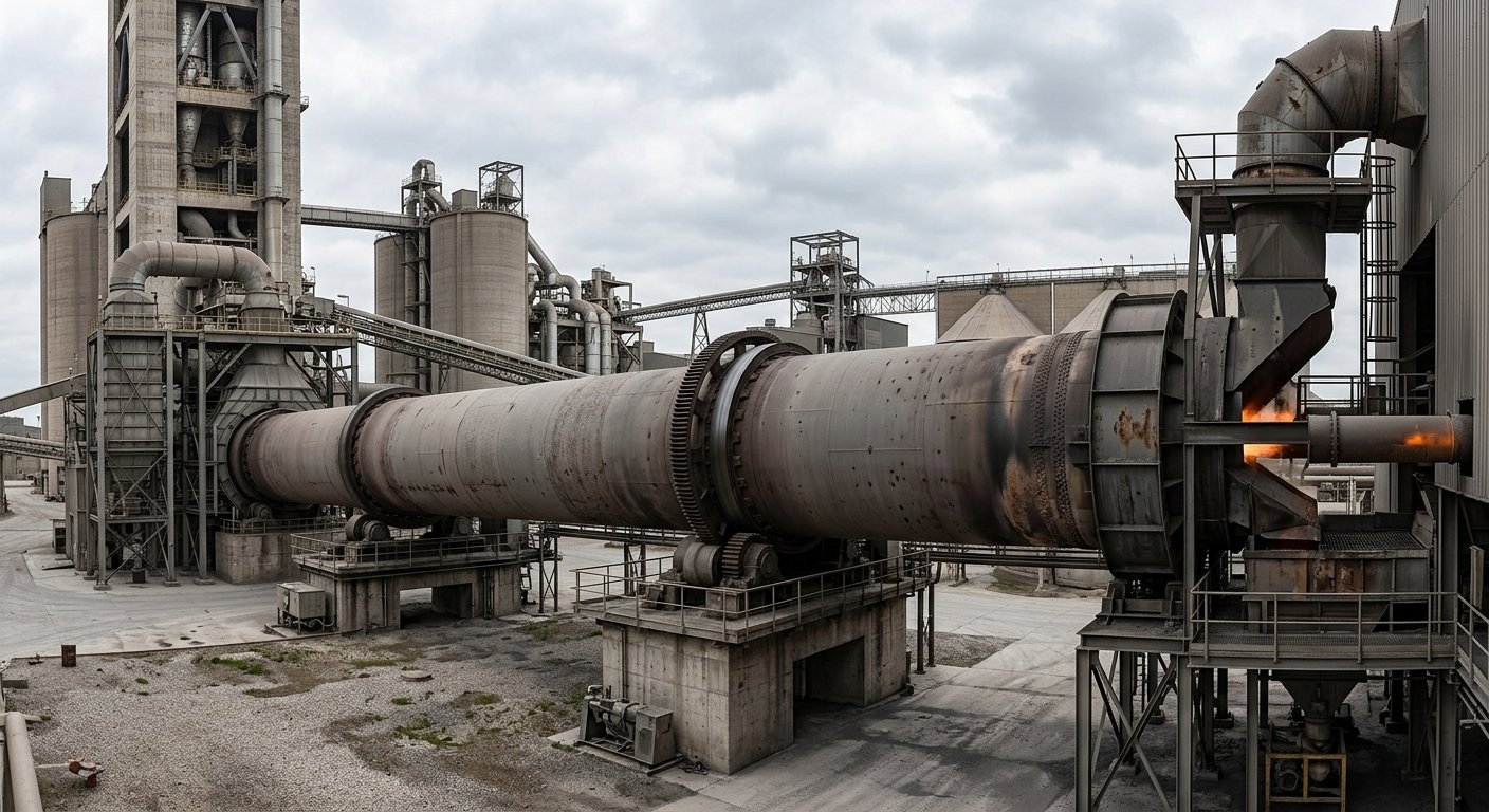
The kiln outlet sits at the discharge end, next to the main burner and the hot clinker bed, the harshest thermal and mechanical environment in the plant, so an outlet seal must tolerate radiant heat, thermal shock, and abrasive clinker dust above all else. This is the hot end.
The numbers set the constraint. The burning-zone material surface runs at roughly 1,430-1,450 °C, and clinker leaves the kiln at about 1,350-1,450 °C as a hard, granular, abrasive solid [4][5]. The seal does not sit in the flame, and some plant designs guide a controlled stream of ambient air around the outlet to cool it, but the element still lives in sustained radiant heat and a stream of clinker fines that act like grit on every rotation. Start-up and shutdown swings add thermal shock on top of the steady heat load.
That combination drives the outlet seal specification. The Oswal kiln outlet sealing system is built around abrasion-resistant construction, thermal-shock tolerance, structural reinforcement, and continuous sealing under heavy dust load [6]. The literature is explicit about why this end matters beyond fuel: "Outlet sealing performance directly influences clinker discharge stability and hood draft control" [6]. A leaking outlet seal disturbs the draft balance at the hood, which the kiln operator feels as a harder kiln to drive.
Conditions at the kiln inlet (feed end) and what they demand
The kiln inlet sits at the feed end where preheated raw meal enters from the preheater, cooler than the outlet but loaded with fine raw-meal dust, so an inlet seal prioritises movement compensation and fine-dust handling over extreme-temperature survival. This is the cooler end, but not a forgiving one.
Conditions differ on every axis. Feed-end kiln gas runs at roughly 1,000-1,100 °C, well below the burning zone, and the incoming raw meal arrives at around 380 °C from the lowest preheater stage [2][4]. The dust is fine raw-meal powder rather than coarse clinker grit, which packs into gaps and abrades seal faces over long service rather than gouging them quickly. Because the feed end is where calcination stabilises, ingress here propagates upstream: inlet false air affects flame shape, temperature profile, and calcination stability [6].
The inlet seal specification follows from this. The Oswal kiln inlet sealing system is engineered for axial movement compensation, radial expansion adaptation, and long-term wear resistance, designed to minimise air ingress at the kiln feed end and protect upstream process stability [6]. The catalogue states the payoff plainly: "Effective inlet sealing directly reduces specific fuel consumption" [6]. The dominant design driver at the inlet is movement and fine-dust durability, not surviving radiant heat.
How to match seal type to each end
Match the seal element to the dominant stress at each end: graphite for the outlet's continuous high temperature, lamella for the inlet's movement and finer dust, and a duplex hybrid wherever one end faces high temperature and high movement at the same time. The choice is a physics question, not a catalogue default.
The three element types map cleanly onto the two stresses that vary between the ends:
- Graphite kiln seal. Graphite-based sealing elements are engineered for high-temperature resistance, continuous sealing contact, and long wear life under dust exposure [6]. Graphite handles the outlet's radiant heat better than steel but is stiffer and more sensitive to rapid thermal cycling, so blocks can crack if shock-loaded. It fits the hot discharge end.
- Lamella kiln seal. Lamella-based sealing elements are overlapping spring-loaded blades that provide flexible adaptation to shell movement and controlled contact pressure, holding sealing continuity despite shell deformation [6]. Lamella flexes well and cycles well but has a lower continuous-temperature limit (around 600 °C in Oswal configurations) [7]. It fits the cooler, movement-led feed end.
- Duplex kiln seal. The Duplex Kiln Sealing System combines a lamella primary interface for axial and radial movement with a graphite secondary interface for high-temperature sealing in one assembly [8]. It is the answer when a single end has both high temperature and high movement, for example an outlet on a high-ovality kiln, or any end with frequent thermal cycling where a single-technology seal loses contact intermittently and leaks.
The table below summarises the conditions and the resulting seal choice for each end.
| Attribute | Kiln inlet (feed end) | Kiln outlet (discharge end) |
|---|---|---|
| Position | Feed / preheater side | Discharge / burner side |
| Typical feed-end gas vs burning-zone temperature | ~1,000-1,100 °C gas [2] | ~1,430-1,450 °C burning zone; clinker out ~1,350-1,450 °C [4][5] |
| Dust character | Fine raw-meal powder | Coarse, abrasive clinker grit |
| Dominant stress on the seal | Axial/radial movement, fine-dust wear | Radiant heat, thermal shock, abrasion |
| Process effect if it leaks | Flame shape, calcination stability, SFC [6] | Clinker discharge stability, hood draft control [6] |
| Primary seal element | Lamella-led | Graphite-led |
| Hybrid case | Duplex if high ovality / frequent cycling | Duplex if high ovality / frequent cycling |
Temperature and dust characteristics are third-party industry typicals [2][4][5]; element demands and the Duplex configuration are per Oswal product specifications [6][7][8]. The right element on any given kiln depends on its measured movement envelope and operating regime. The full element-by-element trade-off, including wear life and retrofit complexity, is in the kiln seal comparison guide.
A combined inlet and outlet sealing strategy
Seal both ends as one programme rather than two isolated fixes: select each end's element for its own conditions, baseline false air section by section before specifying, and monitor after install so the savings hold. The Oswal product literature is direct that piecemeal work underperforms: "Isolated sealing improvements are insufficient. Effective false air control requires an integrated approach" [6].
The reason is practical. A seal specified without a baseline measurement, or installed without follow-up monitoring, rarely holds its design-intent reduction: the element degrades, nobody re-measures, and the savings drift back. Before specifying either end, measure the section-by-section profile using the O2-balance method in how false air is measured in a cement kiln, so the inlet and outlet figures are quantified rather than assumed. The integrated false air control system bundles the inlet seal, the outlet seal, the hood interfaces, and the monitoring into a single retrofit workflow rather than selling a seal in isolation.
The economics support doing both ends together. The Oswal Duplex catalogue cites a return on investment typically within 6 to 18 months on integrated retrofits, driven by lower fuel consumption, lower ID-fan power, and reduced dust leakage at the kiln [8]. The figure depends on baseline false-air percentage and local fuel cost, but with the two seals accounting for the majority of kiln-side ingress [1], they are the two highest-payback elements in any sealing programme.
If you are specifying a seal for a specific kiln end, or scoping an inlet-plus-outlet retrofit, Oswal's engineering consulting team baselines the section-by-section false-air profile and matches each end's element to its measured conditions on-site.
Common questions about this topic
The kiln inlet seal sits at the cooler feed end and handles fine raw-meal dust and shell movement; the kiln outlet seal sits at the hot discharge end beside the burner and handles radiant heat, thermal shock, and abrasive clinker dust. Because the conditions differ, the seal designs differ: the [kiln inlet sealing system](/en/products/kiln-inlet-sealing-system) prioritises axial and radial movement compensation, while the [kiln outlet sealing system](/en/products/kiln-outlet-sealing-system) prioritises abrasion resistance and thermal-shock tolerance. The two are the two largest false-air entry points on the kiln.
A graphite-led seal is the usual choice for the kiln outlet, because [graphite-based sealing elements](/en/products/graphite-based-sealing-elements) handle the discharge end's continuous high temperature and abrasive clinker dust better than steel-blade designs. On a high-ovality kiln or one with frequent thermal cycling, a [Duplex Kiln Sealing System](/en/products/duplex-kiln-sealing-system) is often better, because it adds a lamella interface to absorb the movement that pure graphite handles poorly.
A lamella-led seal is the usual choice for the kiln inlet, because [lamella-based sealing elements](/en/products/lamella-based-sealing-elements) flex to absorb the feed end's axial and radial shell movement and tolerate thermal cycling, and the inlet's lower temperature stays within the lamella material limit. The dominant design driver at the cooler feed end is movement and fine-dust durability, not surviving radiant heat.
No. The feed end and discharge end have different temperatures, different dust, and different movement, so the same element is rarely optimal at both. The better approach is to specify each end for its own conditions and seal both as one programme; the [integrated false air control](/en/products/integrated-false-air-control) system selects the element per end and combines the inlet seal, outlet seal, and monitoring into a single retrofit.
Sources
- Global Cement Magazine / ITECA, *Kiln Seals* feature (November 2023). Industry field figures for false-air share at the kiln inlet and outlet seals; the ~60-75% combined and ~10% inlet / ~8% outlet extreme-case figures are general industry typicals, not Oswal measurements
- Holderbank Group / Holcim, *Cement Manufacturing: Process Technology*, Volume 2 (Holderbank Cement Course training corpus). Canonical reference for feed-end gas temperature ranges and the 1.5-2.5 kcal/kg-per-% false-air penalty convention.
- N. A. Madlool, R. Saidur, M. S. Hossain, N. A. Rahim, "A critical review on energy use and savings in the cement industries," *Renewable and Sustainable Energy Reviews* 15(4), 2011, pp. 2042-2060
- INFINITY FOR CEMENT EQUIPMENT, *The Thermal Journey of Cement Clinker* (general industry reference for burning-zone and discharge temperatures and preheated raw-meal temperature)
- SHYY, *Cement Kiln Temperature: Key to High-Quality Clinker* (general industry reference; clinker calcination and discharge temperature ranges)
- Oswal Engineers, *Kiln Sealing Systems: Global Benchmark in False Air Control* (product catalogue, `OSWAL_kilnseal.pdf`). Source for the inlet and outlet sealing system demands and the element-type descriptions
- Oswal Engineers, *Kiln Sealing Systems* lamella element specification (`OSWAL_kilnseal.pdf`); lamella continuous-temperature limit per Oswal product configuration.
- Oswal Engineers, *Duplex Kiln Sealing System* (product catalogue, `KilnSeal_DuplexType_OK_CAT.pdf`). Source for the hybrid lamella + graphite configuration and the 6-18 month integrated-retrofit payback range
Related Articles
Discuss Your Sealing Requirements
Our engineering team can help identify the right sealing solution for your application.
Contact Engineering Team“Wherever high-temperature rotary kilns operate under controlled atmosphere, Oswal sealing systems ensure energy efficiency and process stability.”